Apparatus and method for sputtering a target using a magnet unit

Inactive Publication Date: 2014-05-01
ACE TECH
View PDF3 Cites 3 Cited by
  • Summary
  • Abstract
  • Description
  • Claims
  • Application Information

AI Technical Summary

Benefits of technology

The invention is about a new sputtering apparatus and method that can make the deposition of material more uniform on the target object. This is achieved by rotating the source and swinging the magnet unit, which increases the lifespan of the source and reduces the deposition thickness on the target object.

Problems solved by technology

There are numerous types of sputtering apparatuses available, an example of which is disclosed in Korean Patent Publication No. 2012-39856, but in many cases, the lifespan of the deposited material is short, and there are severe deviations in deposition thickness on the target object.

Method used


Image

  • Apparatus and method for sputtering a target using a magnet unit
  • Apparatus and method for sputtering a target using a magnet unit
  • Apparatus and method for sputtering a target using a magnet unit

Examples


Embodiment Construction

[0014]As the present invention allows for various changes and numerous embodiments, particular embodiments will be illustrated in the drawings and described in detail in the written description. However, this is not intended to limit the present invention to particular modes of practice, and it is to be appreciated that all changes, equivalents, and substitutes that do not depart from the spirit and technical scope of the present invention are encompassed in the present invention. In describing the drawings, like reference numerals are used for like elements.

[0015]Certain embodiments of the invention will be described below in more detail with reference to the accompanying drawings.

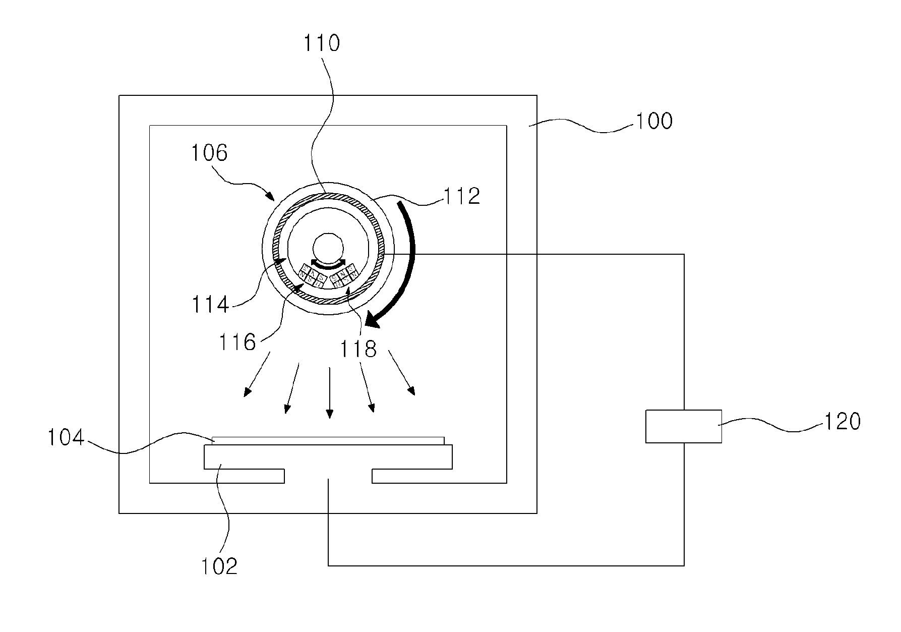
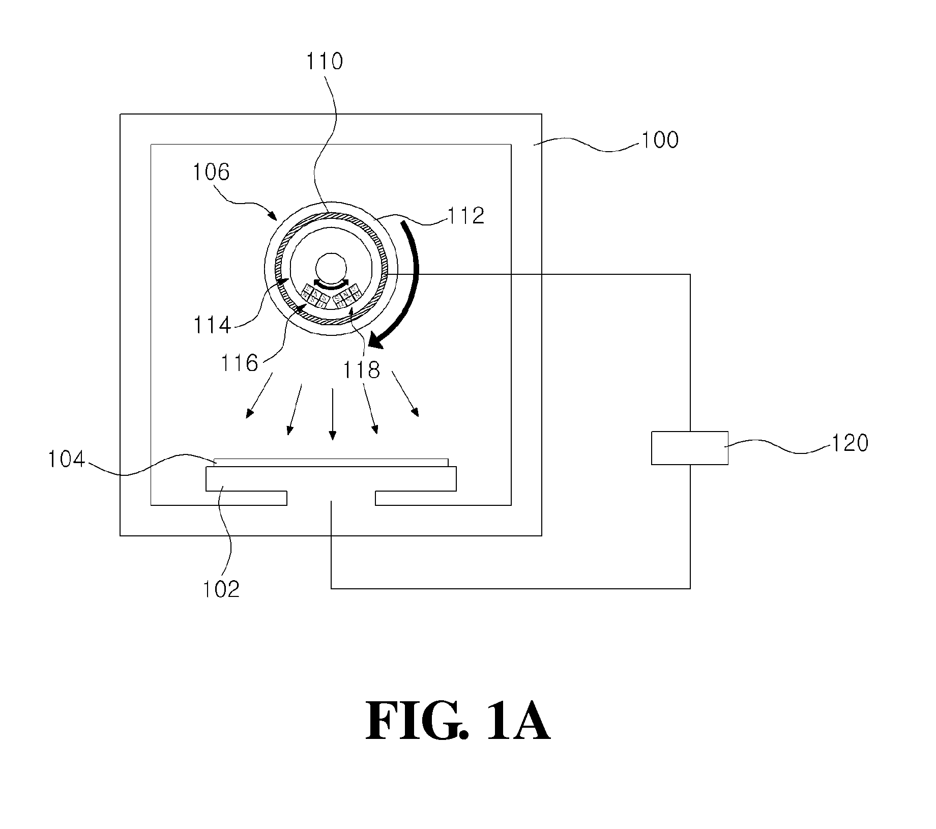
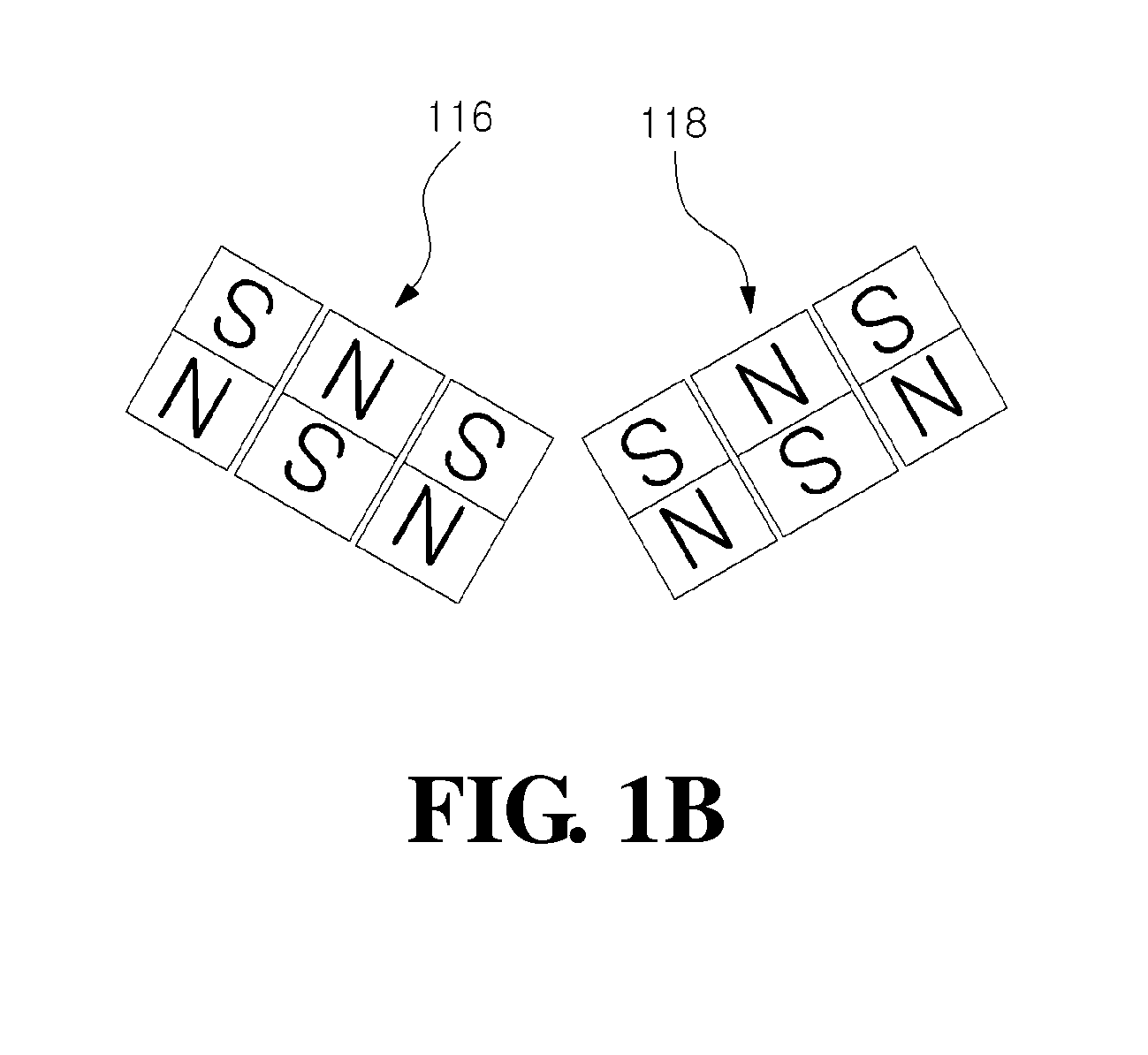
[0016]FIG. 1A and FIG. 1B are cross-sectional views schematically illustrating a sputtering apparatus according to a first disclosed embodiment of the invention, and FIG. 2A and FIG. 2B are diagrams illustrating the operation of a targeting module according to an embodiment of the invention.

[0017]Referrin...


PUM

PropertyMeasurementUnit
Thicknessaaaaaaaaaa
Magnetic fieldaaaaaaaaaa
Perimeteraaaaaaaaaa

Abstract

A sputtering apparatus and method are disclosed which can reduce deviations in the deposition thickness on the target object. The sputtering apparatus may include a chamber body and a targeting module. The targeting module may be positioned inside the chamber body and may include a source and at least one magnet unit, where the magnet unit may be configured to generate a magnetic field. Here, the magnet unit can be made to swing during a sputtering process.

Description

CROSS-REFERENCE TO RELATED APPLICATIONS[0001]This application claims the benefit of Korean Patent Application No. 10-2012-0119885, filed with the Korean Intellectual Property Office on Oct. 26, 2012, the disclosure of which is incorporated herein by reference in its entirety.TECHNICAL BACKGROUND[0002]The present invention relates to an apparatus and method for sputtering a target by using a magnet unit.RELATED ART[0003]A sputtering apparatus refers to an apparatus that applies sputtering on a target for a depositing process. There are numerous types of sputtering apparatuses available, an example of which is disclosed in Korean Patent Publication No. 2012-39856, but in many cases, the lifespan of the deposited material is short, and there are severe deviations in deposition thickness on the target object.SUMMARY[0004]An aspect of the invention is to provide a sputtering apparatus and method that can reduce deviations in deposition thickness on the target object.[0005]To achieve the ...

Claims


Application Information

Patent Timeline
IPC IPC(8): C23C14/35
CPCH01J37/3405C23C14/35H01J37/3455H01J37/3435
Inventor KIM, MYOUNG-HOJUNG, MYUNG-JOON
Owner ACE TECH
Why Eureka
Try Eureka