Electric brake system for vehicle

US20140117749A1Active Publication Date: 2014-05-01HL MANDO CORP

Image

  • Electric brake system for vehicle
  • Electric brake system for vehicle
  • Electric brake system for vehicle

Examples


Embodiment Construction

[0032]Reference will now be made in detail to the embodiments of the present invention, examples of which are illustrated in the accompanying drawings, The terms used in the specification and appended claims should not be interpreted as limited to general and dictionary meanings, but should be construed based on the meanings and concepts according to the spirit of the present invention on the basis of the principle that the inventor is permitted to define appropriate terms for best explanation. The preferred embodiments described in the specification and shown in the drawings are purely illustrative and are not intended to represent all aspects of the invention. Therefore, it should be understood that various equivalents and modifications may be made without departing from the spirit of the invention at the time of filing of this application.

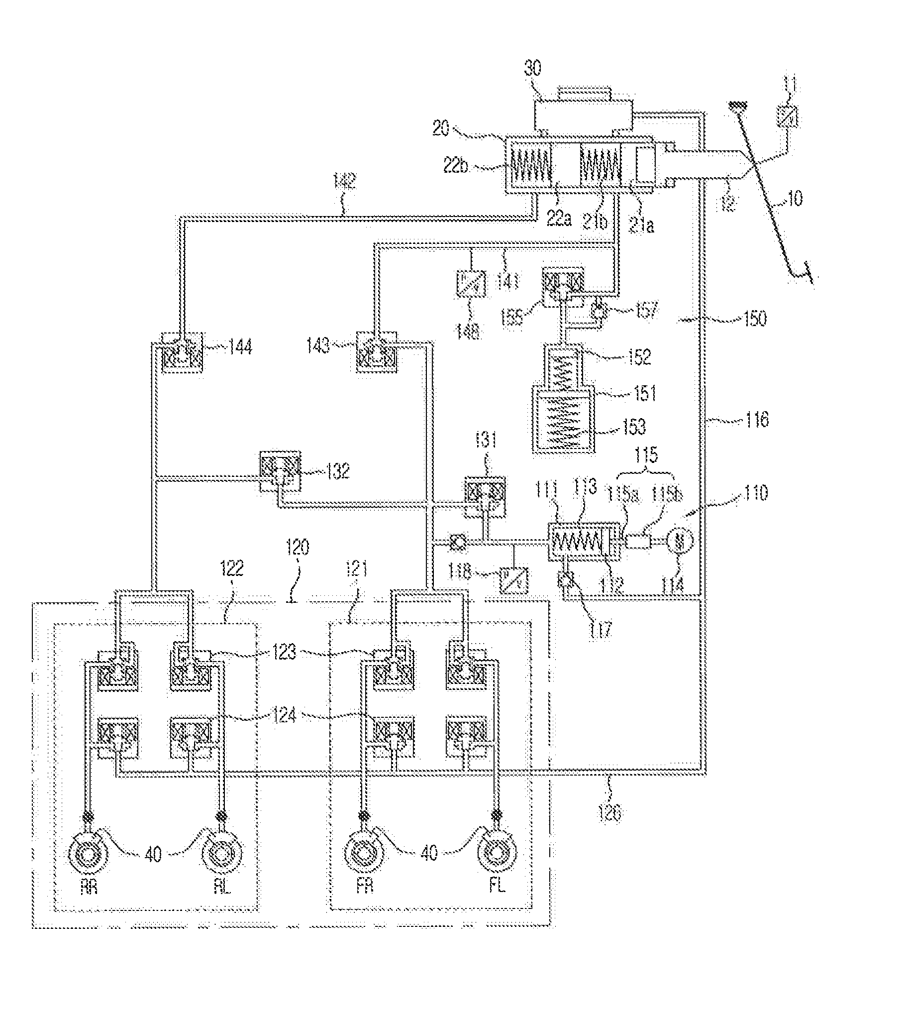
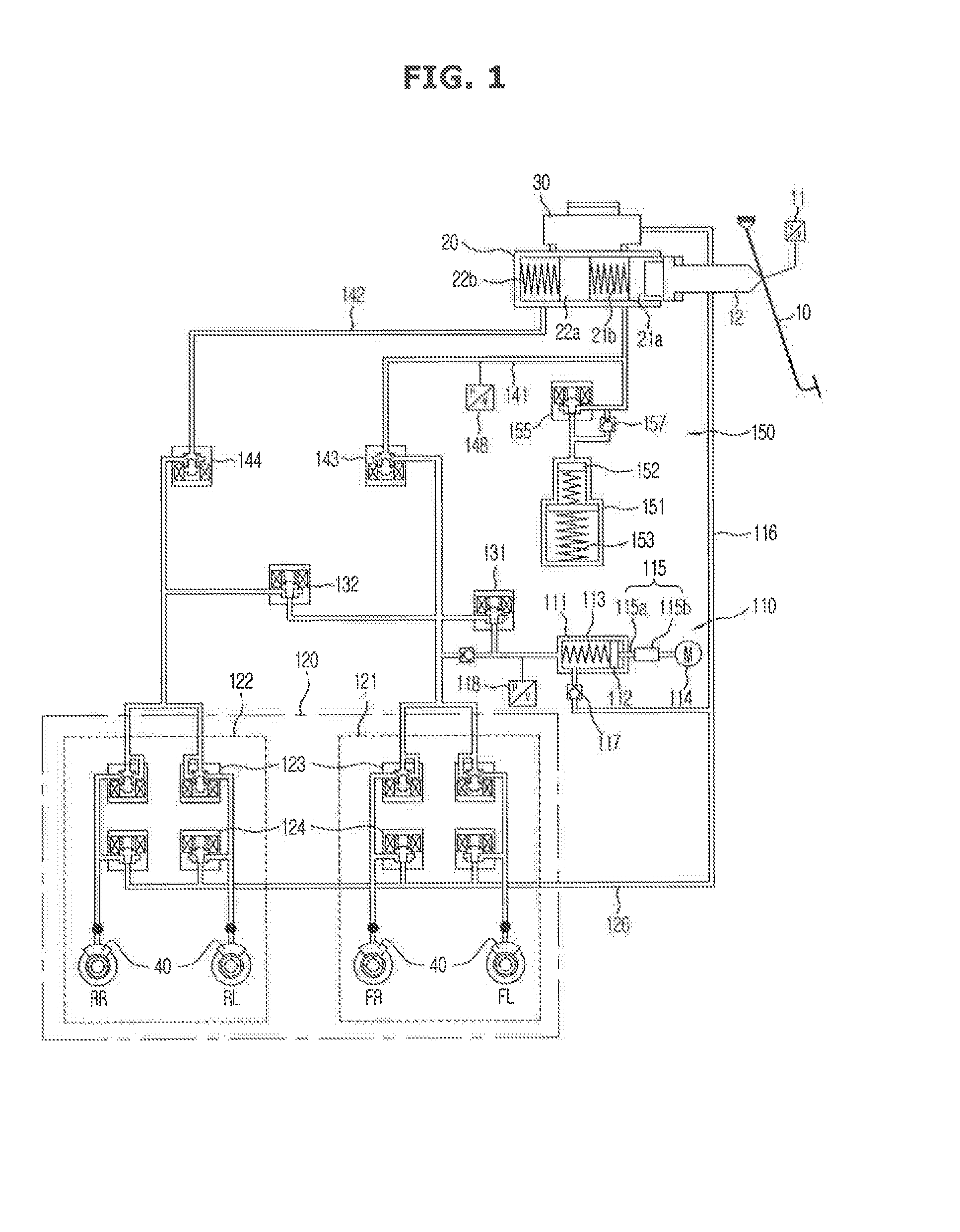
[0033]FIG. 1 is a view showing a hydraulic circuit of an electric brake system for a vehicle according to an embodiment of the present inventio...


PUM


Abstract

Disclosed herein is an electric brake system for a vehicle including a reservoir, a master cylinder, an input rod, and a pedal displacement sensor. The electric brake system includes a pressure supply unit to receive oil and to output an electrical signal through the pedal displacement sensor, a hydraulic control unit to perform braking of a wheel, first and second switching valves connected to a channel connecting the pressure supply unit to the hydraulic control unit, a simulator connected to the master cylinder, and an electronic control unit to control the motor and the valves. The pressure supply unit includes a pressure chamber, a hydraulic piston arranged in the pressure chamber, a hydraulic spring to elastically support the hydraulic piston, the motor to generate rotational force, and a ball-screw member to convert rotational motion of the motor into rectilinear motion. The hydraulic piston is connected to the screw.

Description

CROSS-REFERENCE TO RELATED APPLICATION(S)[0001]This application claims the benefit of Korean Patent Application No. 2012-0121858, filed on Oct. 31, 2012 in the Korean Intellectual Property Office, the disclosure of which is incorporated herein by reference.BACKGROUND[0002]1. Field[0003]Embodiments of the present invention relate to an electric brake system which has a simplified structure and allows precise pressure control.[0004]2. Description of the Related Art[0005]A brake system for braking of a vehicle is essentially mounted on a vehicle, and various systems have recently been proposed to obtain stronger and more stable braking force. Examples of brake systems include an anti-lock braking system (ABS), a brake traction control system (BTCS), and a vehicle dynamic control system (VDC). The ABS prevents wheels from skidding upon braking. The BTCS prevents slippage of driving wheels during rapid acceleration from a stop or upon sudden acceleration of a vehicle. The VDC maintains a...

Claims


Application Information

Patent Timeline
01 May 2014
Publication
US20140117749A1
IPC
B60T13/74
CPC
B60T13/745; B60T7/042; B60T8/4031; B60T8/4081; B60T13/662; B60T13/686; B60T11/24; B60T13/74
Inventors
YANG, I JIN; CHOI, SEONG HO