
Current differential protection

Active Publication Date: 2014-05-01
GENERAL ELECTRIC CO
View PDF0 Cites 17 Cited by
  • Summary
  • Abstract
  • Description
  • Claims
  • Application Information

AI Technical Summary

Benefits of technology

The present invention is a current differential protection system for a multi-terminal power line that includes a current sensor, controller, and fault detection module. The controller synchronizes the local and remote terminals and detects a fault when a differential current exceeds a threshold value. The controller exchanges time stamp data with remote terminals and uses an upper range clock and lower range clock to determine local time measurements. An average time offset is calculated and used to determine phase and frequency signals for the upper and lower range clocks. This system ensures efficient and accurate protection of a multi-terminal power line.

Problems solved by technology

Generally such measurements are only somewhat synchronized because of difficulty in accurately synchronizing sampling clocks physically separated by large distances.
Conventional uses of digital communications to synchronize sampling clocks at remote locations have accuracies limited by uncertainties in the message delivery time.
In particular, digital communications can have different delays in different directions between a pair of locations which lead to an error in clock synchronization.
Utilizing geographical positioning system (GPS) is one solution, however, it needs additional hardware and increases cost.
Communication between various terminals at various locations is another solution; however, the main challenge in communication is caused by a clock rollover.
Since the clocks have limits on maximum time, it results in independent clock rollovers which make multi-terminal clocks converge to a stable but non-synchronized status in which clocks are evenly dispersed along the whole clock range.

Method used


Image

  • Current differential protection
  • Current differential protection
  • Current differential protection

Examples


Embodiment Construction

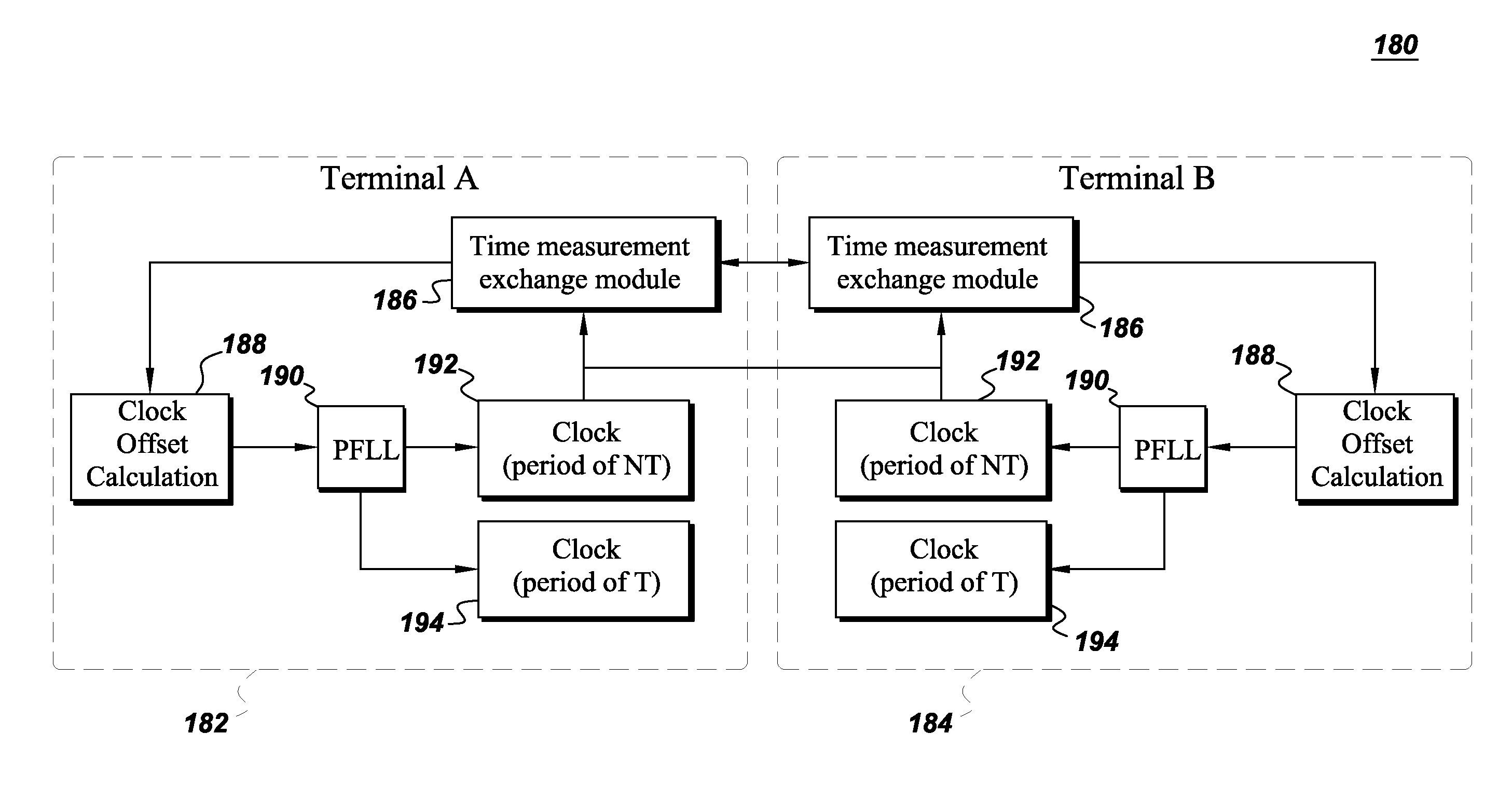
[0016]The embodiments described herein are directed to a power system protection system that enables synchronization of clocks at multiple terminals of a transmission system. While embodiments of the clock synchronization will be described in the context of the transmission system, it will be appreciated by those skilled in the art that the system can be used for other applications such as a power distribution system, power relays, determinations of sequences of events, economic power dispatch, and any other situation requiring synchronization of clocks.

[0017]As used herein, the terms “module” or “controller” refers to software, hardware, or firmware, or any combination of these, or any system, process, or functionality that performs or facilitates the processes described herein.

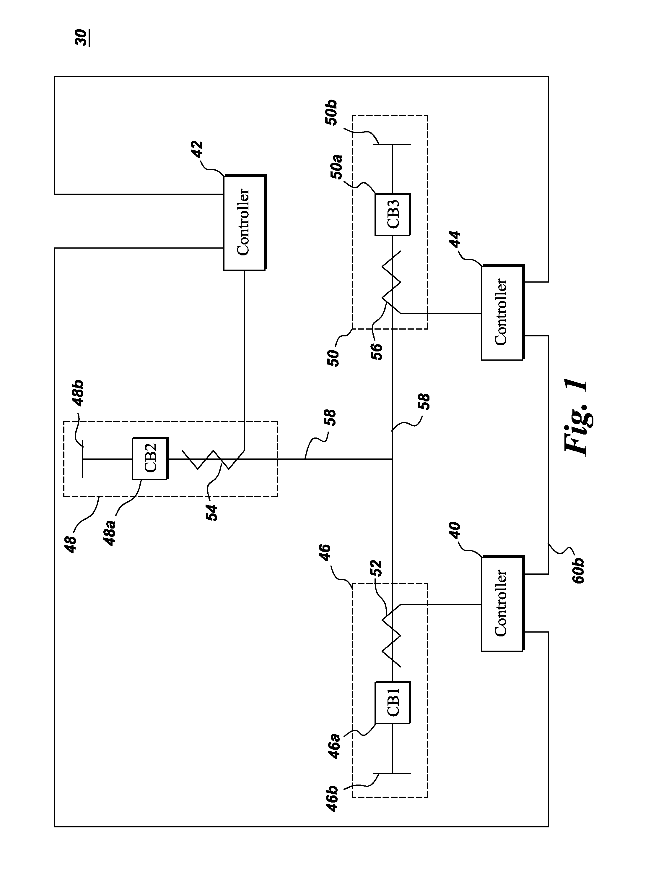
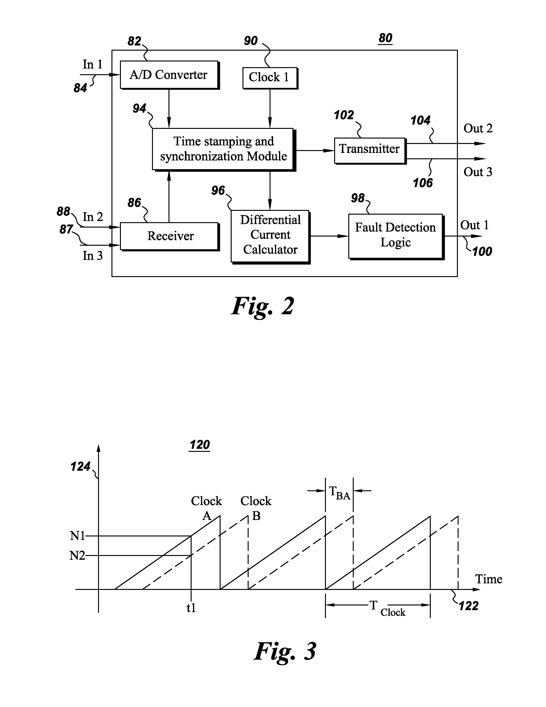
[0018]FIG. 1 is a block diagram of a multi-terminal transmission system 30 including three terminals 46, 48 and 50 with a power line 58 and communication lines 60a, 60b, and 60c therebetween. In one embodime...


PUM


Abstract

A current differential protection system for a multi-terminal power line includes a current sensor for sensing a current at a local terminal, a controller for time synchronizing the local terminal and remote terminals, and a fault detection module to detect a fault in the multi-terminal power line if a differential current exceeds a threshold value. The controller includes a time measurement exchange module for exchanging time stamp data with remote terminals, an upper range clock for exchanging time stamp data with remote terminals and a lower range clock for indexing the current at the local terminal. A first time period of the upper range clock is N times a second time period of the lower range clock where N is a number of multi-terminals. The controller includes a clock offset calculation module for determining an average time offset based on time stamp data from remote terminals and the local terminal.

Description

BACKGROUND[0001]Embodiments of the system relate generally to an electric power system and more specifically to protection systems for the electric power system.[0002]Many power system monitoring, protection, and control functions could be performed more efficiently and accurately if power system digital measurements at multiple locations were synchronized. Generally such measurements are only somewhat synchronized because of difficulty in accurately synchronizing sampling clocks physically separated by large distances. Conventional uses of digital communications to synchronize sampling clocks at remote locations have accuracies limited by uncertainties in the message delivery time. In particular, digital communications can have different delays in different directions between a pair of locations which lead to an error in clock synchronization.[0003]In addition to being important for multi-terminal transmission lines, clock synchronization is important in many other applications suc...

Claims


Application Information

Patent Timeline
IPC IPC(8): G01R31/08
CPCH02H1/0061G01R31/08H02H7/263H02H3/305H02H3/28
Inventor PAN, YANPREMERLANI, WILLIAM JAMES
Owner GENERAL ELECTRIC CO
Learn More