
Telecommunication surge protector system

a technology for telecommunications and surge protectors, applied in emergency protection devices, basic electric elements, selection arrangements, etc., can solve problems such as affecting the safety of users, and emitted particles, and causing damage through clear housings

Inactive Publication Date: 2014-05-01
IWASAKI SEAN
View PDF19 Cites 2 Cited by
  • Summary
  • Abstract
  • Description
  • Claims
  • Application Information

AI Technical Summary

Benefits of technology

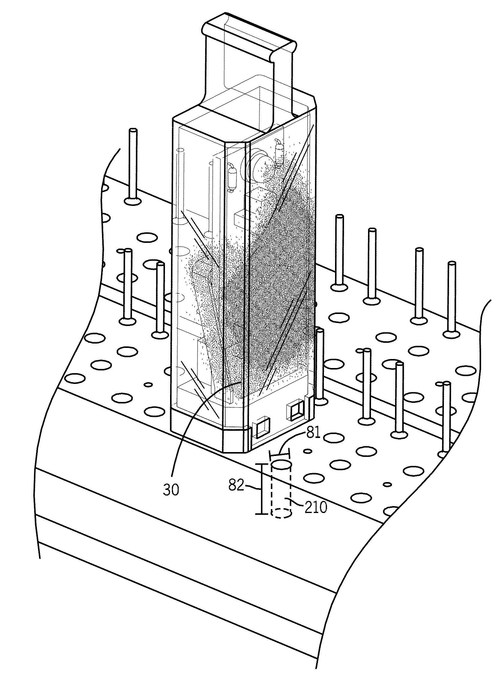
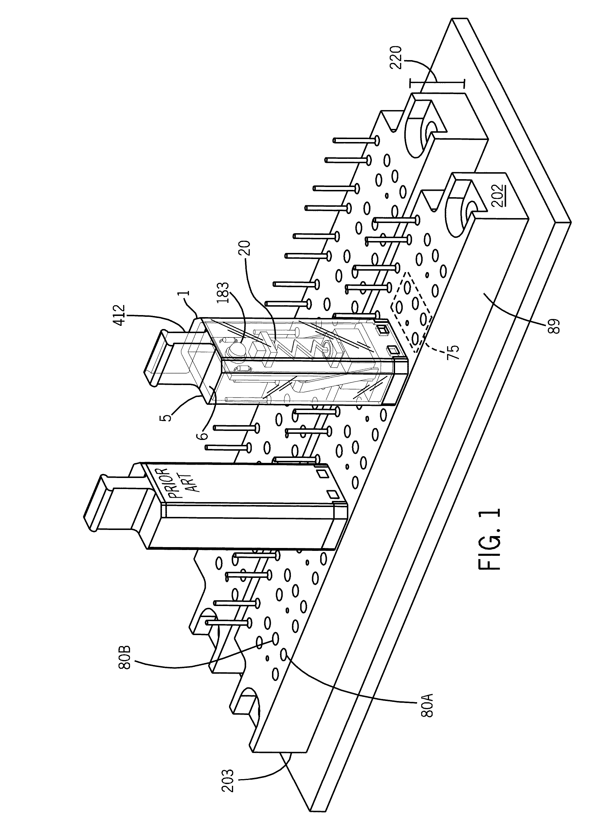
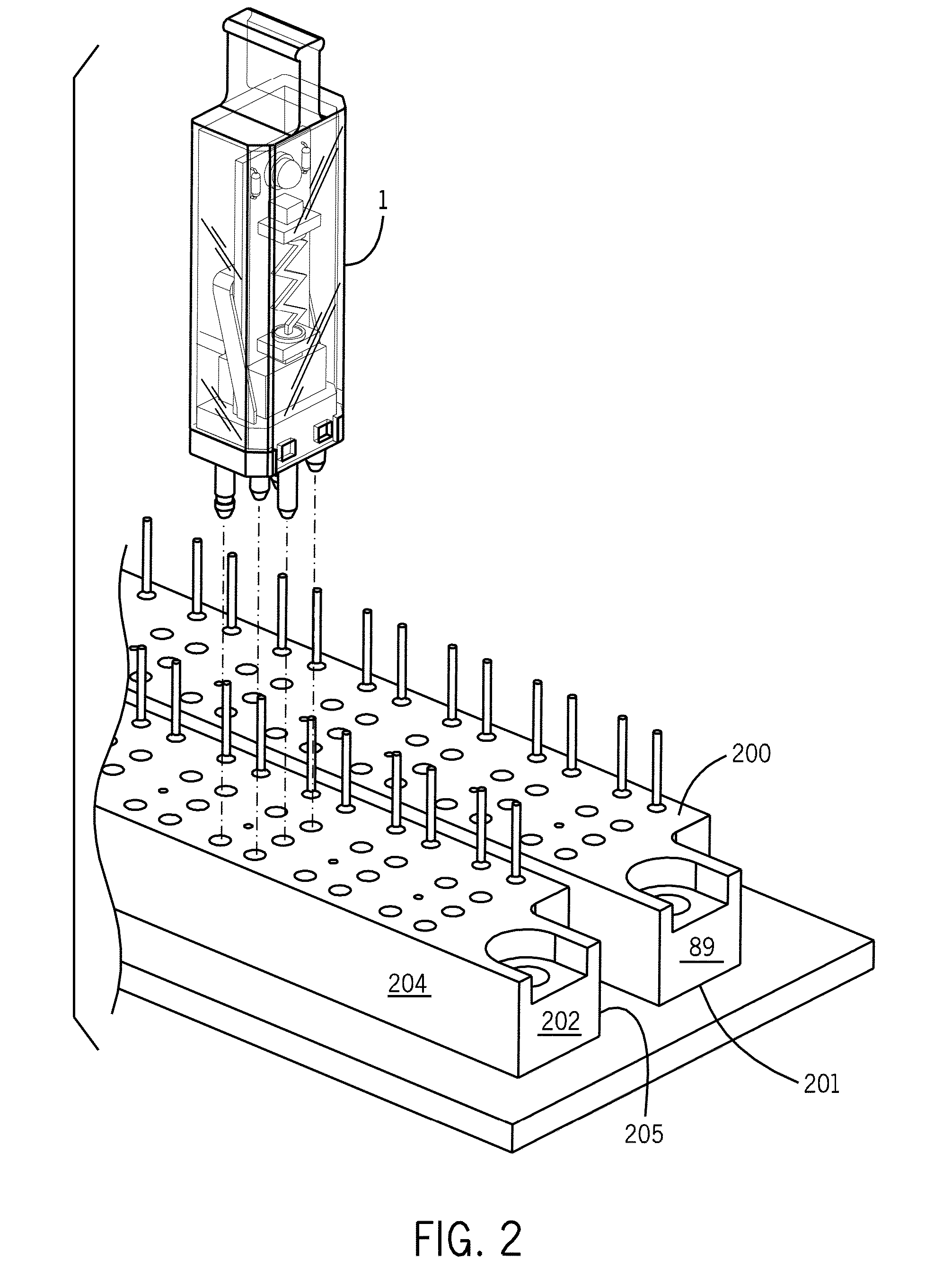
The present invention provides a telecommunication surge protector system with a transparent housing that allows easy visual inspection of the system without the need for removing the Surge protector from the socket. The system includes a fusible link that creates visible damage when the Surge protector is damaged due to an unexpected heightened electrical surge, indicating the need for replacement. The Surge protector can also incorporate non-surge protection components to provide visual indication on the status of the Surge protector and the connected communication transmission service. The clear housing of the Surge protector allows the technician to visually identify the non-surge protection component's status indicators without the need to remove the Surge protector from the system, simplifying maintenance and repair of the communication transmission service. The five pin Surge protector has fusing, voltage-limiting circuitry, current limiting circuitry, and non-surge protection components located within the transparent housing, allowing easy differentiation of a working five pin Surge protector from a non-working one.

Problems solved by technology

Damage to the fusible link is visible through the transparent housing.
When the telecommunication surge protector is damaged due to an unexpected heightened electrical surge, the fusible link will fail and create black smoke, emit particles, and show visible damage through a clear housing.

Method used


Image

  • Telecommunication surge protector system
  • Telecommunication surge protector system
  • Telecommunication surge protector system

Examples


Embodiment Construction

[0039]A telecommunication surge protector system is provided. The surge protector has a transparent housing having four peripheral pins and a single central pin. The four peripheral pins are electrically connected to surge / non-surge protection components and communication transmission lines. The surge protector further has a fusible link, a voltage limiting component and a current liming component. Damage to the fusible link is visible through the transparent housing. The transparent nature of the housing also provides visual indication of the status of the communication transmission service with respect to the non-surge protection components. The present five pin surge protector is inserted into a socket of the telecommunication system. The socket of the present system has five openings, all of which are shallow; therein preventing the accidental insertion of a non-fusing surge protector pin into the system.

[0040]Referring now to FIG. 1, a telecommunication surge protector 1 is pro...


PUM


Abstract

A telecommunication surge protector system is provided. The surge protector has a transparent housing having four peripheral pins and a single central pin. The four peripheral pins are electrically connected to surge / non-surge protection components and communication transmission lines. The surge protector further has a fusible link, a voltage limiting component and a current liming component. Damage to the fusible link is visible through the transparent housing. The transparent nature of the housing also provides visual indication of the status of the communication transmission service with respect to the non-surge protection components. The present five pin surge protector is inserted into a socket of the telecommunication system. The socket of the present system has five openings, all of which are shallow; therein preventing the accidental insertion of a non-fusing surge protector pin into the system.

Description

CROSS REFERENCE TO RELATED APPLICATIONS[0001]The present application is based on U.S. provisional application No. 61 / 553,310 filed on Oct. 31, 2011, currently co-pending, the entire contents of which are incorporated by reference. Applicant claims the priority benefit of the 61 / 553,310 application.BACKGROUND OF THE INVENTION[0002]A telecommunication surge protector system is provided. The surge protector has a transparent housing having four peripheral pins and a single central pin. The four peripheral pins are electrically connected to surge / non-surge protection components and communication transmission lines. The surge protector further has a fusible link, a voltage limiting component and a current liming component. Damage to the fusible link is visible through the transparent housing. The transparent nature of the housing also provides visual indication of the status of the communication transmission service with respect to the non-surge protection components. The present five pi...

Claims


Application Information

Patent Timeline
Patent Type & Authority Applications(United States)
IPC IPC(8): H01H85/20H01H85/32
CPCH01H85/32H01H85/2015H01H85/30H01H85/44H04Q1/146
Inventor IWASAKI, SEAN
Owner IWASAKI SEAN
Learn More