
Method and device for machine diagnosis, especially for transmission diagnosis

a machine diagnosis and transmission diagnosis technology, applied in the direction of mechanical roughness/irregularity measurement, instruments, nuclear elements, etc., can solve the problems of contaminated oil stream flowing in the duct with ferromagnetic particles, magnetic short circuit, etc., to achieve long life, low production and operating costs, and robust device structure

Inactive Publication Date: 2005-03-29
ZF FRIEDRICHSHAFEN AG
View PDF9 Cites 0 Cited by
  • Summary
  • Abstract
  • Description
  • Claims
  • Application Information

AI Technical Summary

Benefits of technology

Other advantages of the device according to the invention are as follows:its mode of operation does not depend on the transport fluid;its mode of operation does not depend on the duct cross-section,its mode of operation is largely independent of the Reynolds number of the transport fluid and of air included in it,the structure of the device is robust and it therefore has a long life.production and operating costs are low; andon-line transmission or machine diagnosis is possible.
The binary measurement signal of the device, according to the invention, serves as a timely indication of high wear of ferritic moving parts of a transmission or a machine. This information can be used as a warning, which detects not yet visible damage and prevents a possible future total failure of the transmission or machine. Both repair costs / repurchasing of the transmission or machine and even a possible loss of earnings, for vehicles used commercially, can be reduced considerably by the device according to the invention. Moreover, the device, according to the invention, used, for example, in a transmission of a motor vehicle, can increase safety by avoiding transmission damage while driving.

Problems solved by technology

The oil stream flowing in the duct is contaminated with ferromagnetic particles.
As soon as a certain quantity of ferritic wear particles have accumulated on the capturing magnet, a magnetic short-circuit results.

Method used


Image

  • Method and device for machine diagnosis, especially for transmission diagnosis
  • Method and device for machine diagnosis, especially for transmission diagnosis

Examples


Embodiment Construction

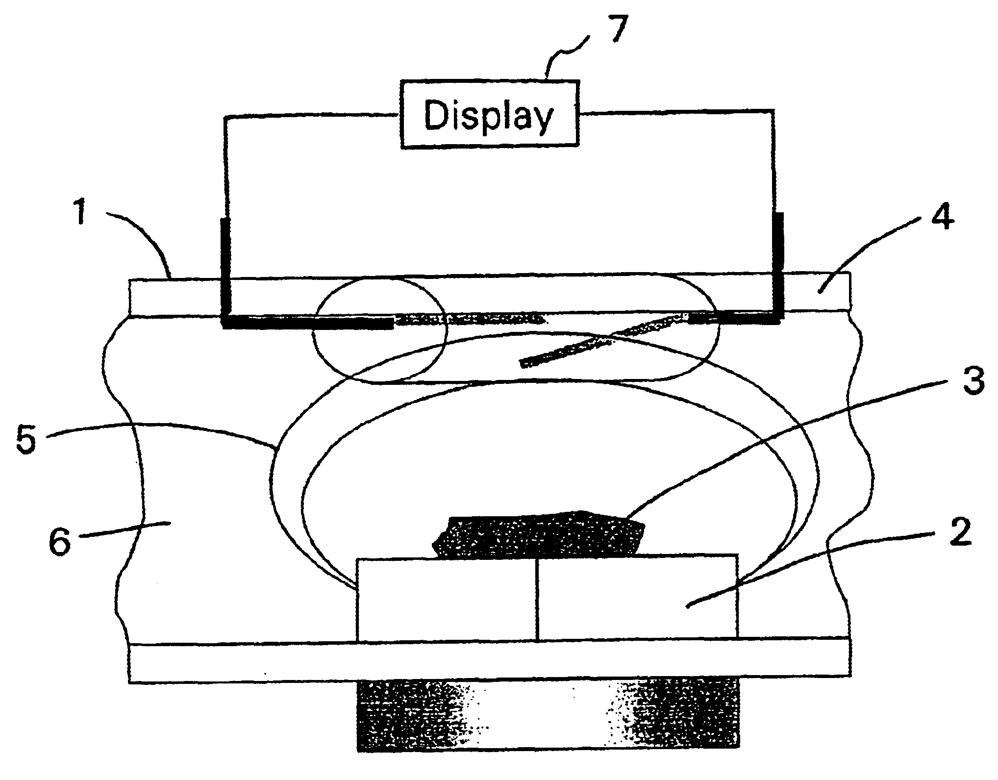
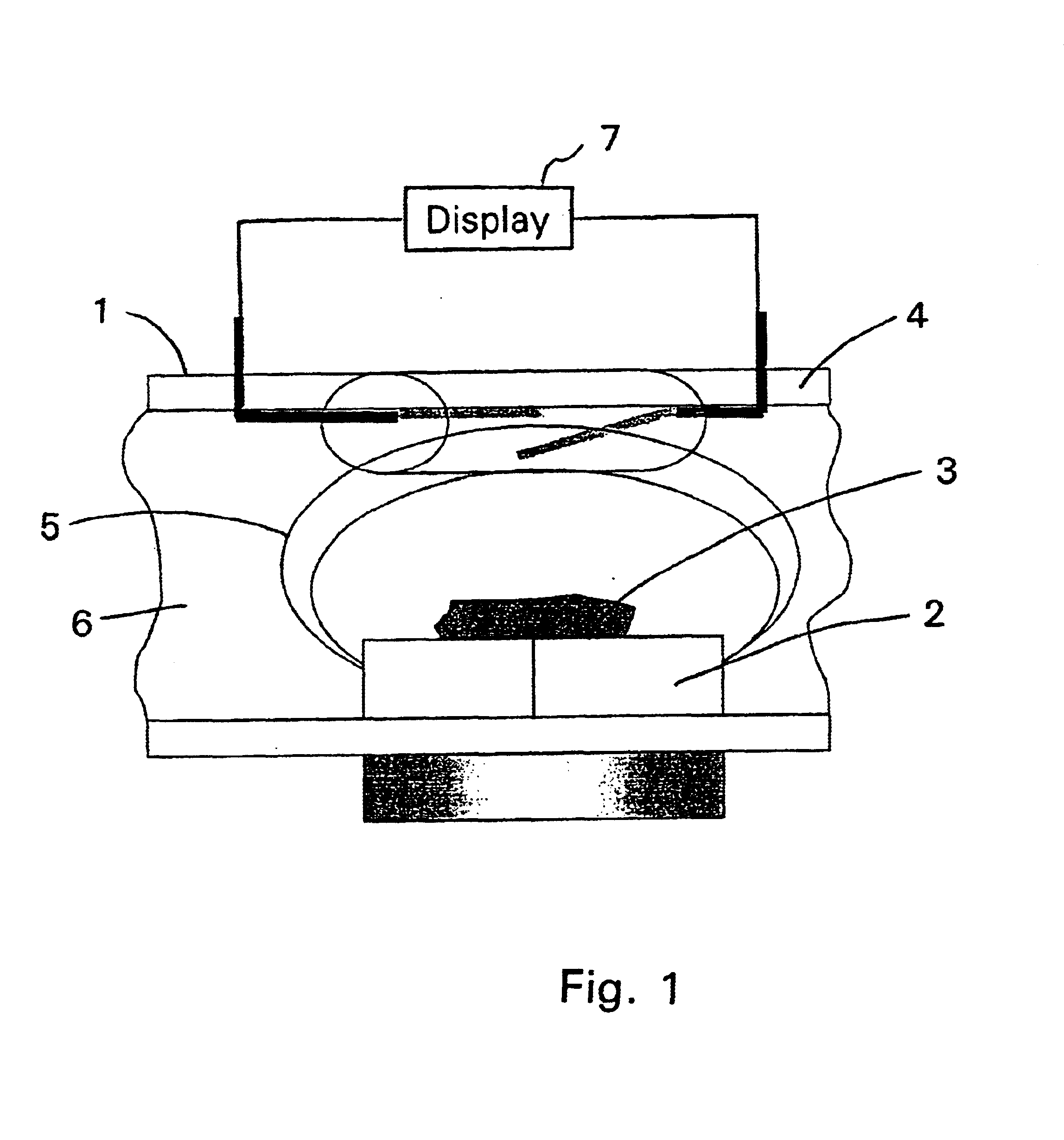
The Figure shows a longitudinal section through part of an oil duct 4 of a transmission. A capturing magnet or permanent magnet 2 is arranged on the lower side of the oil duct 4. Opposite this permanent magnet 2, on the upper side of the oil duct 4, is a reed contact 1. As shown in the Figure, the magnetic field lines 5 emerge from the permanent magnet 2 and extend outwards through the cross-section of the oil duct. Ferritic wear particles 3, in the oil stream 6, are attracted by the permanent magnet 2 and accumulate on its surface. If enough ferritic wear particles 3 are present on the surface of the permanent magnet 2, the magnetic field lines run directly through the ferritic wear particles 3 from the North to the South pole. The result of this is that the density of the magnetic field lines, the so-termed magnetic flux density, decreases in the cross-section of the oil duct 4. This change of the magnetic flux density is detected by the reed contact 1 and, when its value exceeds ...


PUM

PropertyMeasurementUnit
magnetic flux densityaaaaaaaaaa
transmissionaaaaaaaaaa
Hall effectaaaaaaaaaa

Abstract

A method for machine diagnosis and, in particular, for transmission diagnosis of a machine or motor vehicle. The measurement system comprises a capturing magnet (2), on the surface of which the ferritic wear particles (3) to be detected accumulate. A binary measurement signal is produced by a reed contact (1) arranged opposite the capturing magnet (2). This measurement gives an indication of the condition of the machine or transmission.

Description

FIELD OF THE INVENTIONThe present invention concerns a method for machine diagnosis and, in particular, for diagnosis of a machine or transmission of a motor vehicle. In addition the invention concerns a device for implementing the method.BACKGROUND OF THE INVENTIONIn modern machines and vehicle transmissions it is nowadays sought to fill these with engine oil and transmission oil once during their lifetime, and the life of such a transmission being, for example, typically on the order of 1 million kilometers.The machine or transmission oil serves to lubricate and cool all the mechanical elements. Since it is never changed, it is exceptionally suitable for machine or transmission diagnosis since, over the course of time, all kinds of abrasion particles accumulate in the oil. Consequently, analysis of the machine or transmission oil provides information about the condition of the machine or transmission.In this, ferritic wear is of particularly great importance since in almost any ty...

Claims


Application Information

Patent Timeline
Patent Type & Authority Patents(United States)
IPC IPC(8): G01N15/06G01M13/02G01N33/28G01N33/26
CPCG01N33/2858G01N15/0656G01M13/02F16H57/0404
Inventor REMMLINGER, HUBERTINGENBLEEK, ROBERTSCHUWERK, GABRIELESCHMITZ, ROLF
Owner ZF FRIEDRICHSHAFEN AG
Learn More