Successive approximation a/d converter

Active Publication Date: 2014-05-01
ASAHI KASEI ELECTRONICS CO LTD
View PDF15 Cites 0 Cited by
  • Summary
  • Abstract
  • Description
  • Claims
  • Application Information

AI Technical Summary

Benefits of technology

[0059]According to the present invention, a robust successive approximation A/D converter that has a simple configuration and does not fall into metastable states, compared with the conventional successive app

Problems solved by technology

In other words, the comparator cannot perform the judgment operation and hence there is the possibility of not being able to transit to the next state.
In such an A/D converter, if a difference between the voltage of the storage node SN and the reference voltage VC is in a level wher

Method used


Image

  • Successive approximation a/d converter
  • Successive approximation a/d converter
  • Successive approximation a/d converter

Examples


Example

First Embodiment

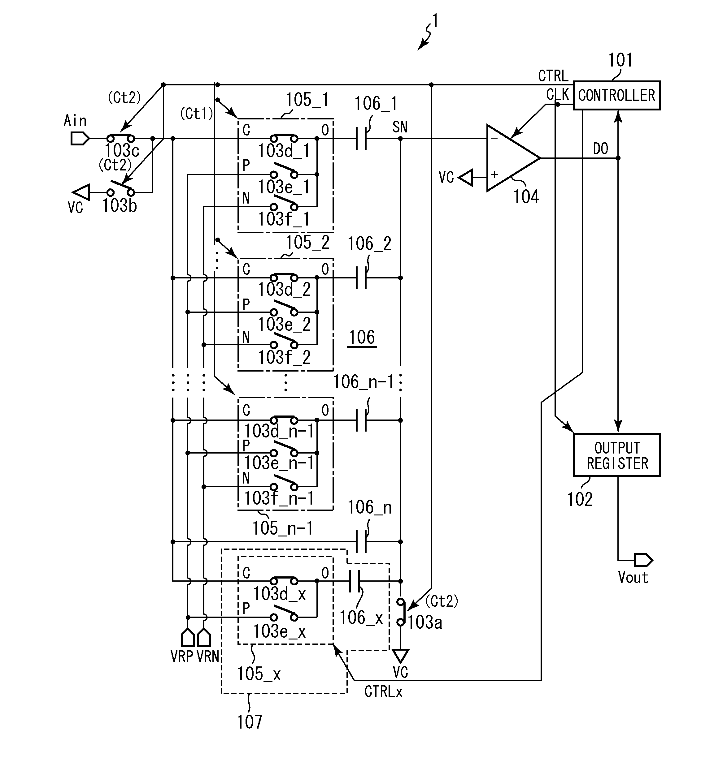
[0070]FIG. 1 is a circuit configuration diagram for describing a first embodiment of a successive approximation A / D converter according to the present invention.

[0071]A successive approximation A / D converter 1 of the first embodiment is an asynchronous successive approximation A / D converter for A / D converting an analog input signal Ain to an n-bit digital output signal Vout (where n is a natural number of 3 or more) to perform an asynchronous operation.

[0072]The successive approximation A / D converter 1 of the present invention includes a capacitor array 106 having multiple capacitors each of which is so configured that one end side is connected to a common conductor, respectively. The successive approximation A / D converter makes a successive comparison of a holding voltage on each corresponding capacitor of the multiple capacitors in this capacitor array 106 with a predetermined reference voltage to obtain a digital output signal corresponding to the analog input sig...

Example

Second Embodiment

[0192]Referring next to the drawings, a second embodiment of the present invention will be described.

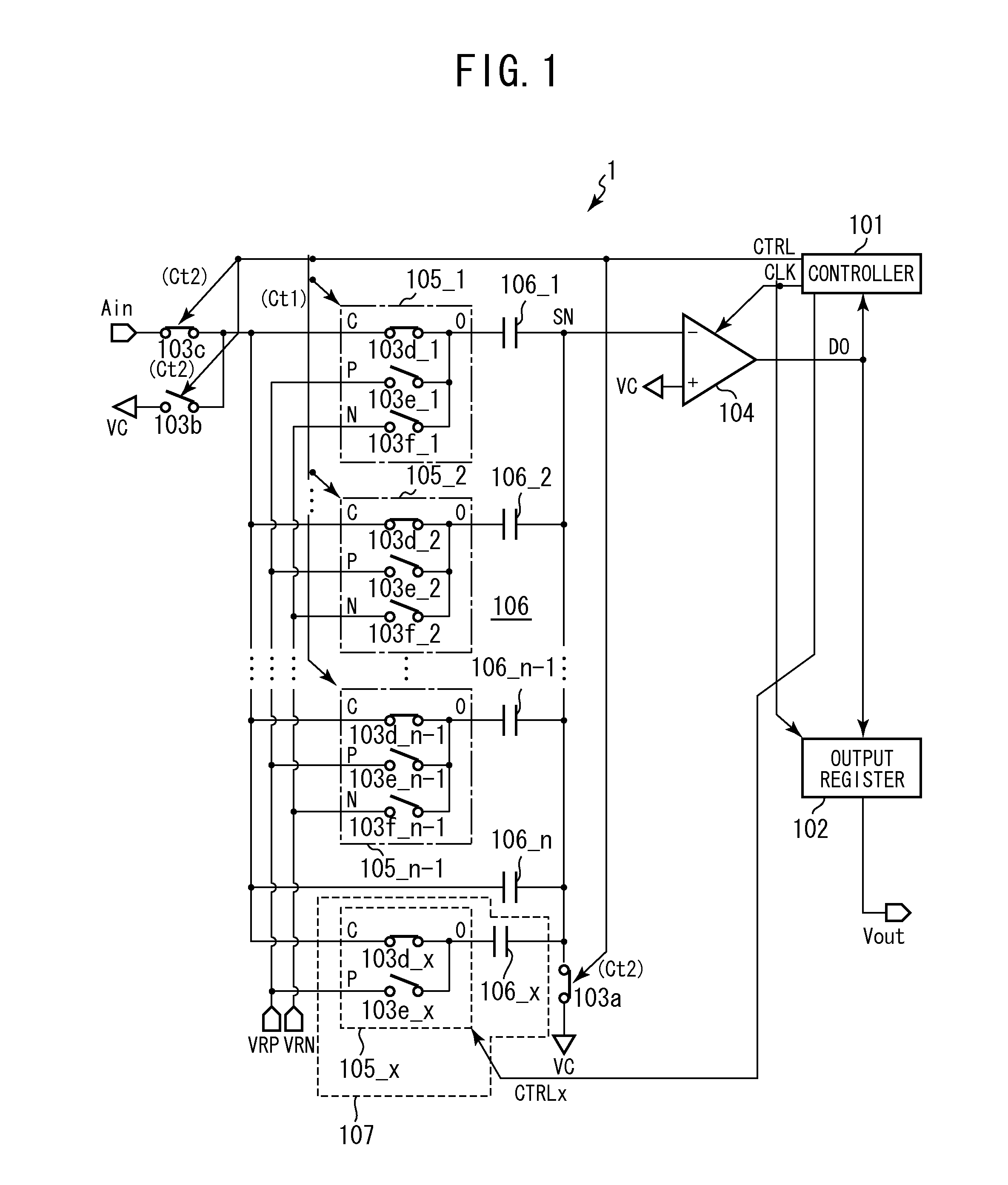
[0193]FIG. 5 is a circuit configuration diagram for describing a second embodiment of a successive approximation A / D converter according to the present invention.

[0194]In comparison with the successive approximation A / D converter 1 of the first embodiment shown in FIG. 1, a successive approximation A / D converter 2 of the second embodiment is different in including a second controller 108 instead of the voltage application part 107. In the following description, components having the same functions as those in the successive approximation A / D converter 1 of the first embodiment shown in FIG. 1 are given the same reference numerals to omit redundant description.

[0195]In other words, the successive approximation A / D converter of the second embodiment includes the second controller 108 for converting and outputting, to the first controller 101, a judging output signal DO...


PUM


Abstract

The successive approximation A/D converter includes: switch groups 1051 to 105x each of which is connected to the other end of each corresponding capacitor of capacitors 1061 to 106x to selectively switch a capacitor to be applied to a successive comparison in response to a switch group control signal Ct1; a comparator 104 for making a successive comparison of a comparison voltage VSN based on a holding voltage on each corresponding capacitor, selected through the switch groups from among the capacitors, with a predetermined reference voltage VC in synchronization with a timing control signal CLK to obtain a judgment output according to the comparison result; and a voltage application part 107 for applying a predetermined voltage to the comparison voltage based on a form-of-voltage application control signal Ct2 for a predetermined period when a predetermined time has elapsed after the successive comparison.

Description

TECHNICAL FIELD[0001]The present invention relates to a successive approximation A / D converter applied to an input circuit of digital equipment or the like, and more specifically to a robust successive approximation A / D converter that does not fall into metastable states.BACKGROUND ART[0002]As a conventional successive approximation A / D converter, for example, there is a successive approximation A / D converter disclosed in Non-Patent Document 1. This successive approximation A / D converter A / D converts an analog input signal Ain into an n-bit digital output signal Vout (where n is a natural number of 3 or more).[0003]FIG. 7 is a circuit configuration diagram for describing a conventional successive approximation A / D converter shown in Patent Document 3 (see FIG. 5).[0004]As shown in FIG. 7, one capacitor 506_1 whose capacitance value is set to a predetermined reference capacitance C is provided in this successive approximation A / D converter. Further, (n−2) capacitors 506_2 to 506_(n−1...

Claims


Application Information

Patent Timeline
IPC IPC(8): H03M1/36
CPCH03M1/36H03M1/0678H03M1/468
Inventor NAKANISHI, JUNYA
Owner ASAHI KASEI ELECTRONICS CO LTD
Why Eureka
Try Eureka