
Three dimensional radar system using usual radars installed in sea facilities

a radar system and three-dimensional technology, applied in the direction of antennas, instruments, movable body antenna adaptation, etc., can solve the problems of large amount of expenses required to install air radar, damage may be anticipated in private vessels, and the application of aircraft flying through the air cannot be realized near ports to monitor and acquire any information, etc., to maximize mutual synergy effect and low price

Active Publication Date: 2014-05-01
KOREA INST OF OCEAN SCI & TECH
View PDF24 Cites 2 Cited by
  • Summary
  • Abstract
  • Description
  • Claims
  • Application Information

AI Technical Summary

Benefits of technology

The present invention allows for quick management of emergency situations in main ports and adjacent seas, as well as secure control of port security. Additionally, it allows for the creation of integrated air surveillance systems and the use of low-cost radar systems. Furthermore, it maximizes mutual synergy effects with related industries.

Problems solved by technology

However, any appliances could not be realized to monitor and acquire any information about the aircrafts flying through the air near ports.
Further, when error occurs in the system due to the radar after-image of the aircraft approaching the port, damages may be anticipated in private vessels because port surveillance and control cannot operate in appropriate time.
However, huge amount of expenses is required to install air radar system for air surveillance and control at the same time.
There is not yet developed the system suitable for surveillance of small-sized unmanned aircrafts in the short distance and close ranges air.
Infratechnology such as radar video signal processing technology and data processing technology has been rapidly developed mainly with domestic defense industry, but is still beginning status compared with advanced countries, and could not be developed into civil industrialization because most of domestic radar technology has been treated as military security technology.
The air surveillance radar system for military purposes as above is difficult to use in a narrow range for air surveillance and control, and is very expensive equipment raging from billions of won to tens of billions of won in price.
This system is now used in about 20 countries including Korea, and is very expensive equipment at price of about 15 billion won.

Method used


Image

  • Three dimensional radar system using usual radars installed in sea facilities
  • Three dimensional radar system using usual radars installed in sea facilities
  • Three dimensional radar system using usual radars installed in sea facilities

Examples


Embodiment Construction

[0043]The present invention will now be described more fully hereinafter with reference to the accompanying drawings, in which preferred embodiments of the invention are shown.

[0044]It will be understood that words or terms used in the specification and claims shall not be interpreted as the meaning defined in commonly used dictionaries. It will be further understood that the words or terms should be interpreted as having a meaning that is consistent with their meaning in the context of the relevant art and the technical idea of the invention, based on the principle that an inventor may properly define the meaning of the words or terms to best explain the invention.

As used herein, the singular forms “a”, “an” and “the” are intended to include the plural forms as well, unless the context clearly indicates otherwise.

[0045]The present invention may be embodied in different forms and should not be construed as limited to the embodiments set forth herein. Rather, these embodiments are pr...


PUM


Abstract

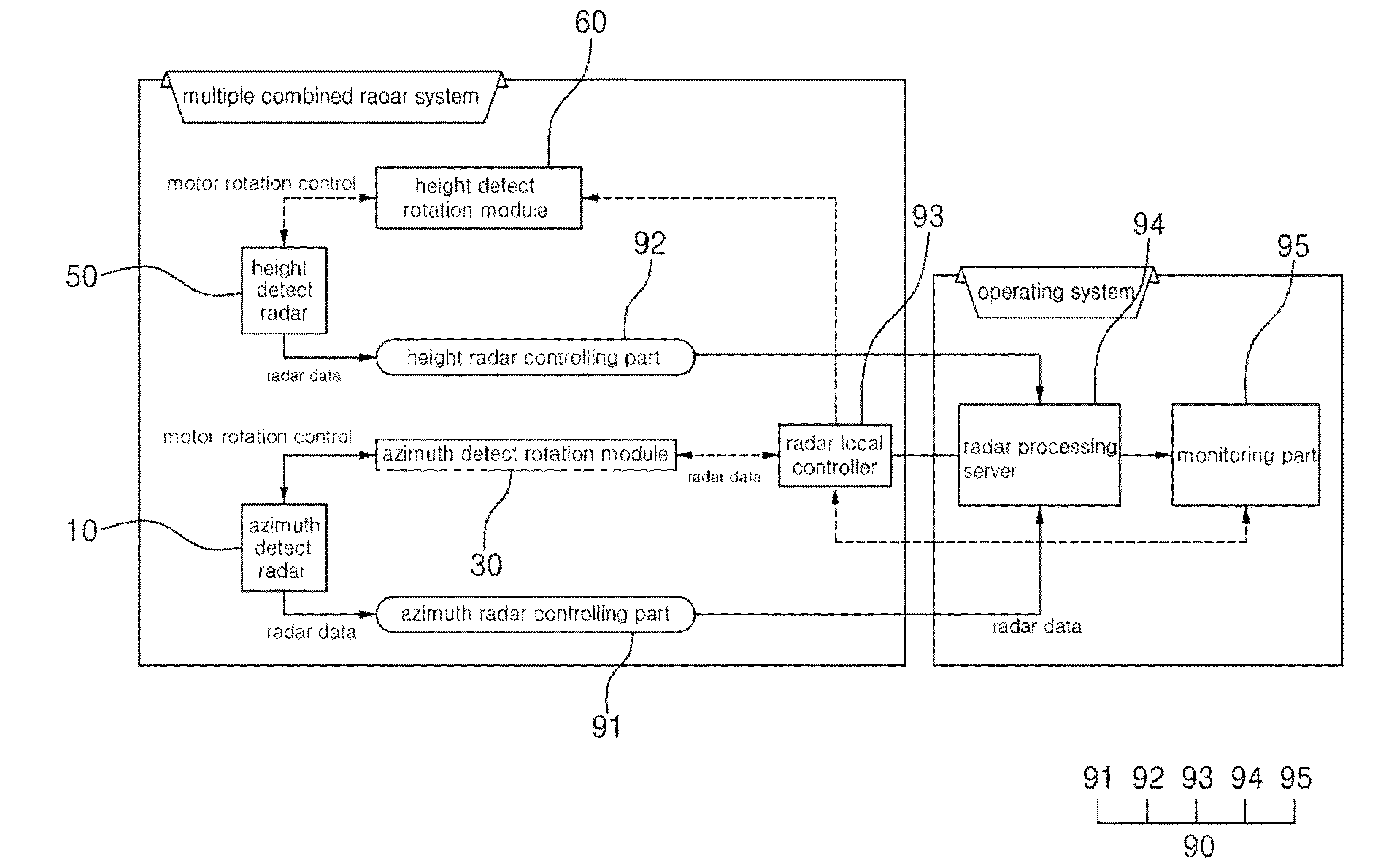
There is provided a three-dimensional radar system by using the combination of commercialized usual radars for vessels at relatively low price so as to enable to strengthen the surveillance capability about aircrafts flying at low altitude and strengthen the surveillance capability on the sea and in the air to protect important facilities of a port with more developed than the conventional surveillance system of monitoring only ships or vessels in a port while overcoming the operational limitation of VTS (Vessel Traffic Service).

Description

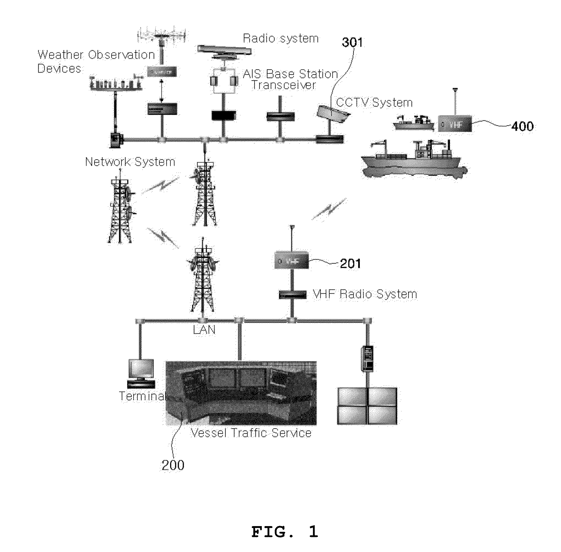
TECHNICAL FIELD [0001]The present invention relates to a three dimensional radar system using radars for vessels to enable to perform port and air surveillance.BACKGROUND ART[0002]VTS (Vessel Traffic Service), which is used to make, arrange, and control overall traffic system projects such as sailing speed, course, directions, and location positioning about all vessels coming in and out of a port within a range of sea, employs a port radar to identify and trace ships and vessels in a port.[0003]As illustrated in FIG. 1, a VTS (200) employs a CCTV (301), a VHF (201), communication devices, and so on in order to control the vessels sailing in the radar-monitoring incapable sea areas and identify the clearness of the vessels. However, any appliances could not be realized to monitor and acquire any information about the aircrafts flying through the air near ports.[0004]Further, when error occurs in the system due to the radar after-image of the aircraft approaching the port, damages ma...

Claims


Application Information

Patent Timeline
IPC IPC(8): G01S13/02
CPCG01S13/02G01S7/03G01S13/426G01S13/87H01Q1/34H01Q3/02H01Q3/26H01Q21/28G01S13/91G01S13/917G01S13/06
Inventor CHO, DEUK JAESUH, SANG HYUN
Owner KOREA INST OF OCEAN SCI & TECH
Learn More