Imaging lens and imaging apparatus using the same

a single-focus imaging and imaging apparatus technology, applied in the field of single-focus imaging lenses, can solve the problems of difficulty in obtaining a high-contrast image lack of appropriateness for downsizing, etc., to achieve satisfactory aberration correction, improve optical performance, and increase the design flexibility for improving various types of aberrations

Inactive Publication Date: 2014-05-01
TIANJIN OFILM OPTO ELECTRONICS CO LTD
View PDF0 Cites 11 Cited by
  • Summary
  • Abstract
  • Description
  • Claims
  • Application Information

AI Technical Summary

Benefits of technology

[0009]In the mean time, there is a demand for an imaging lens having improved optical performance, for example, improved resolution along with the densification of the image sensors.
[0015]The present invention has been developed in view of the circumstances described above, and it is an object of the present invention to provide a compact and bright imaging lens having a wide angle of view and a long back focus, and an imaging apparatus using the same.
[0035]According to the imaging lens and imaging apparatus of the present invention, four lenses are used which are disposed in the order of a negative first lens having a meniscus shape with a convex surface on the object side, a positive second lens having a biconvex shape, a negative third lens having a concave surface on the image side, and a positive fourth lens having a convex surface on the object side from the object side, and arranged to satisfy the conditional expression (1): L12 / f<0.82 and the conditional expression (2): 2.3<L12×R2F2 / f2<10.0 simultaneously, so that a compact and bright optical system having a wide angle of view and a long back focus may be realized.
[0036]That is, the compactness may be realized by the use of a small number of lenses of four, the wide angle of view and the long back focus may both be realized by the use of a lens having a strong negative refractive power as the first lens, and satisfactory aberration correction may be implemented by gradually converging the light beam diffused through the first lens over the second lens to the fourth lens.
[0037]Further, if each of two or more of the first to the fourth Lenses is an aspherical lens having an aspherical surface on one or both surfaces, the design flexibility for improving various types of aberrations is increased, whereby further improved optical performance may be obtained.

Problems solved by technology

The brightness of the imaging lens described in Japanese Unexamined Patent Publication No. 10 (1998)-300906, however, is dark with F5.58 and it is difficult to obtain a high contrast image.
Further, it lacks appropriateness for downsizing because the overall optical length is long in comparison with the focal length.
Further, as the overall optical length is long in comparison with the focal length, it lacks appropriateness for downsizing.
The imaging lenses described in U.S. Pat. No. 6,762,890 and Japanese Patent No. 4416411 have realized sufficient aberration correction and compactness by the use of an aspherical surface, but unable to comply with a brightness level of, for example, F2.2 and lacks telecentricity as the angle between the principal ray of off-axis light beam and the optical axis exceeds 10 degrees.

Method used


Image

  • Imaging lens and imaging apparatus using the same
  • Imaging lens and imaging apparatus using the same
  • Imaging lens and imaging apparatus using the same

Examples


example 1

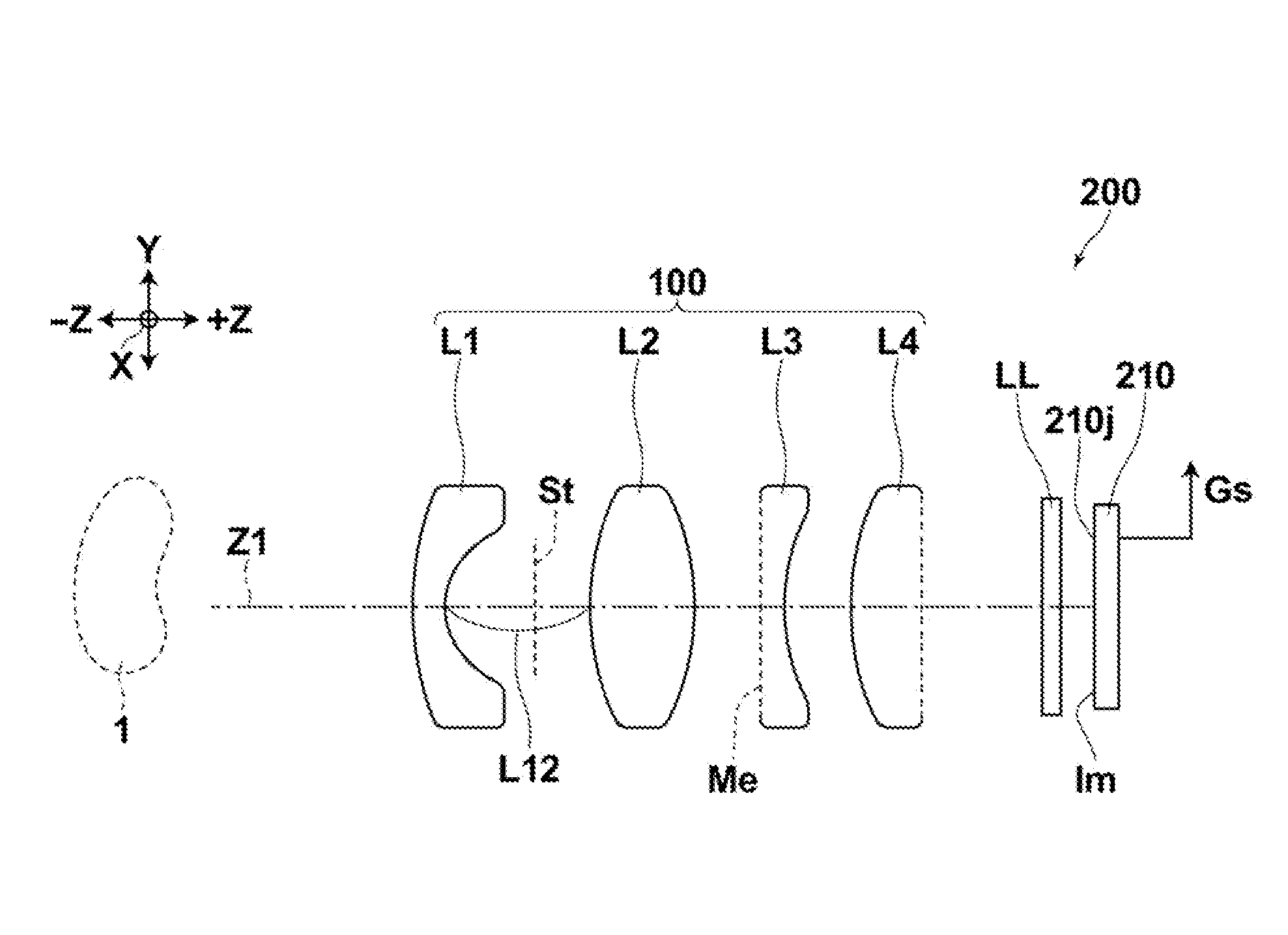
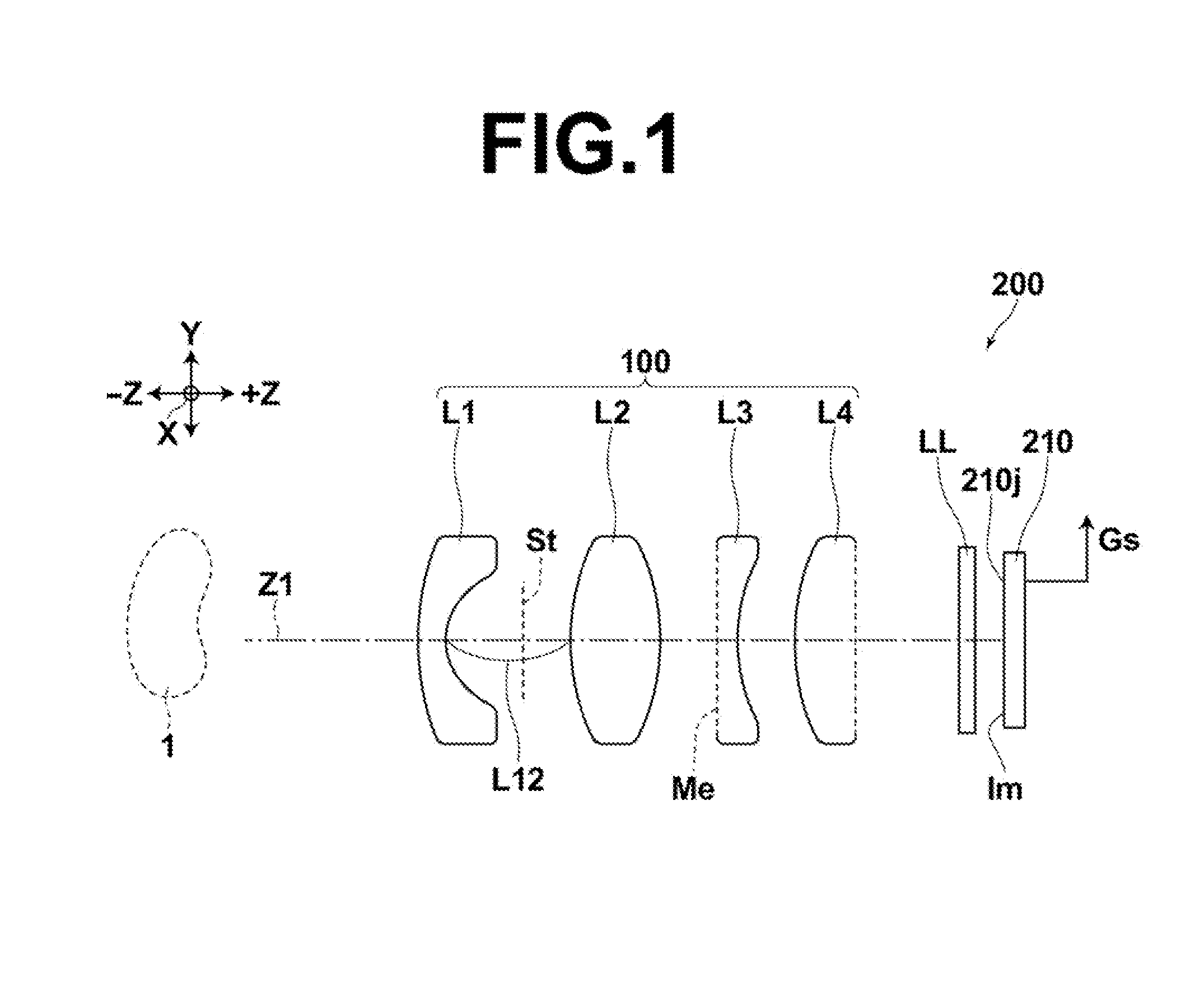
[0134]FIG. 4 is a cross-sectional view of an imaging lens of Example 1, schematically illustrating the configuration thereof with optical paths of light beams passing through the imaging lens.

[0135]The imaging lens of Example 1 is configured to satisfy all of the conditional expressions (1) to (7), and the conditional expression (8).

[0136]Table 1A shows lens data of the imaging lens of Example 1. In the lens data shown in Table 1A, the surface number i represents ith surface number Si in which a number i (i=1, 2, 3, - - - ) is given to each surface in a serially increasing manner toward the image side with the surface on the most object side being taken as the first surface. In Table 1A, the surface number is given also to an aperture stop St, an optical element LL having no power, and an image plane on which an optical image Im is formed.

[0137]The symbol Ri in Table 1A represents the radius of curvature of ith (i=1, 2, 3, - - - ) surface and the symbol Di represents the surface dis...

example 2

[0156]FIG. 5 is a cross-sectional view of an imaging lens of Example 2, schematically illustrating the configuration thereof with the optical paths of center light beam and outermost light beam passing through the imaging lens.

[0157]The imaging lens of Example 2 is configured to satisfy the conditional expressions (1) to (7).

[0158]FIG. 12 illustrates aberrations of the imaging lens of Example 2.

[0159]Table 2A below shows lens data of the imaging lens of Example 2 and Table 2B shows aspherical coefficients of the imaging lens of Example 2.

TABLE 2AExample2Lens DataSiRiDireNdjν dj114.28571.97200.0001.4874970.2322.77141.00100.000(St) 3∞2.37203.060*46.00351.94400.0001.7725049.6*5−12.32590.75604.600*648.84500.60004.2001.6336023.59*73.87590.26900.000*85.56251.80300.0001.5339155.96*9−7.37516.65700.00010∞0.50000.0001.5168064.211∞0.50000.00012∞0.00000.0001. Third surface is aperture stop, twelfth surface is image plane, and tenth to eleventh surface are cover glass, filter, an the like.2. *...

example 3

[0160]FIG. 6 is a cross-sectional view of an imaging lens of Example 3, schematically illustrating the configuration thereof with the optical paths of center light beam and outermost light beam passing through the imaging lens.

[0161]The imaging lens of Example 3 is configured to satisfy the conditional expressions (1) to (7) and conditional expression (8).

[0162]FIG. 13 illustrates aberrations of the imaging lens of Example 3.

[0163]Table 3A below shows lens data of the imaging lens of Example 3, and Table 3B shows aspherical coefficients of the imaging lens of Example 3.

TABLE 3AExample 3Lens DataSiRiDireNdjν dj111.36362.80100.0001.5891361.1422.83962.27300.000(St) 3∞0.50003.65049.57923.93100.0001.7550052.325−5.65791.04004.900*684.39310.97000.0001.8051825.42*73.75380.42905.300*810.55661.77200.0001.7725049.6*9−5.84466.64270.00010∞0.50000.0001.5168064.211∞0.50000.00012∞0.00000.0001. Third surface is aperture stop, twelfth surface is image plane, and tenth to eleventh surface are cover g...


PUM


Abstract

An imaging lens formed of 4 lenses, in which a negative first lens having a meniscus shape with a convex surface on the object side, a biconvex positive second lens, a negative third lens having a concave surface on the image side, and a positive fourth lens having a convex surface on the object side, arranged in order from the object side, and the imaging lens satisfies conditional expressions (1): L12 / f<0.82; (2): 2.3<L12×R2F2 / f2<10.0; (5): −1.3<f1 / f<−0.9; and (6): 48<v1 simultaneously, where, L12 is the air equivalent distance between the first lens and the second lens, f is the focal length of the entire lens system, R2F is the radius of curvature of the object side lens surface of the second lens, f1 is the focal length of the first lens, and v1 is the Abbe number of the first lens with respect to the d-line.

Description

TECHNICAL FIELD[0001]The present invention relates to a single focus imaging lens composed of four lenses and an imaging apparatus using the same.BACKGROUND ART[0002]Heretofore, small and lightweight imaging devices which include a solid-state image sensor, such as a CCD, CMOS, or the like, and a single focus imaging lens have been known. Such imaging devices include, for example, digital cameras, surveillance cameras, in-vehicle cameras, image reading cameras for deficiency detection, individual identification, and the like. As imaging lenses that form an optical image on a light receiving surface of such solid-state image sensors, bright, low distortion, and high resolution imaging lenses while still having a simple structure with a small number of lenses and an appropriate back focus for inserting an optical element, such as a filter or the like, have been known (refer to Japanese Unexamined Patent Publication No. 10 (1998)-300906, Japanese Unexamined Patent Publication No. 2002-...

Claims


Application Information

Patent Timeline
Patent Type & Authority Applications(United States)
IPC IPC(8): G02B13/04G02B13/18
CPCG02B13/04G02B13/18G02B9/04G02B13/004
Inventor MORI, MASAO
Owner TIANJIN OFILM OPTO ELECTRONICS CO LTD
Why Eureka
Try Eureka