Acousto-optic imaging device

a technology of optical imaging and optical probes, applied in the field of optical probes, can solve the problems of increasing the size of the apparatus, the difficulty of real-time image acquisition, or the cost of the apparatus, and achieves the effects of increasing the number of piezoelectric elements of the probe, increasing the throughput of signal processing, and improving the resolution

Inactive Publication Date: 2014-05-01
PANASONIC CORP
View PDF0 Cites 3 Cited by
  • Summary
  • Abstract
  • Description
  • Claims
  • Application Information

AI Technical Summary

Benefits of technology

[0006]Highly-developed medical technology has created demand for three-dimensional imaging of a tissue or organ inside a subject with higher resolution. To this end, it is necessary to further increase the number of piezoelectric elements of the probe. However, when the number of the piezoelectric elements is increased, a greater throughput for signal processing is necessary for the beam forming, so that it is difficult to obtain an image in real time, or a signal processing circuit which has a very high computational power is necessary, so that the size of the apparatus increases or the cost of the apparatus increases.

Problems solved by technology

However, when the number of the piezoelectric elements is increased, a greater throughput for signal processing is necessary for the beam forming, so that it is difficult to obtain an image in real time, or a signal processing circuit which has a very high computational power is necessary, so that the size of the apparatus increases or the cost of the apparatus increases.

Method used


Image

  • Acousto-optic imaging device
  • Acousto-optic imaging device
  • Acousto-optic imaging device

Examples


first embodiment

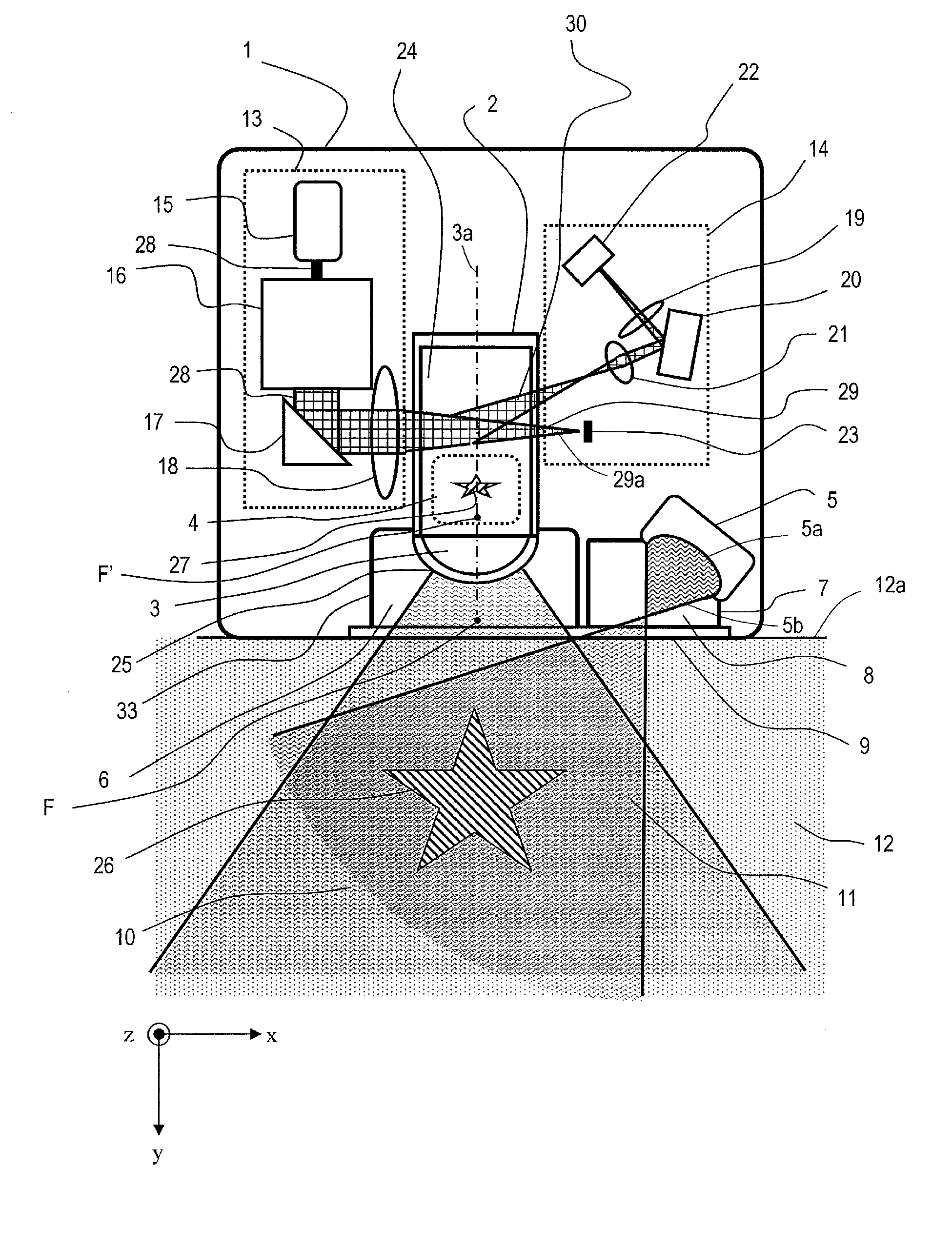
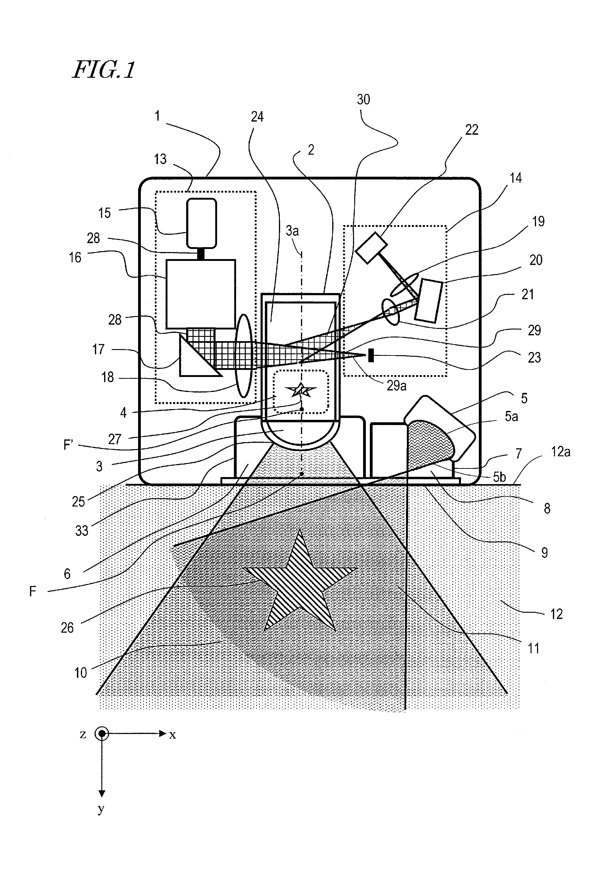
[0045]FIG. 1 is a schematic diagram showing the first embodiment of the acousto-optic imaging device of the present invention. The acousto-optic imaging device 1 shown in FIG. 1 produces an image of an internal tissue of a subject 12, such as a human being or animal, for example. For the sake of simple illustration, an organ inside the subject 12 is schematically shown as a star-shaped reflector 26. In the drawings mentioned below, the reflector 26 is shown as a two-dimensional object which is parallel to the drawing sheet but, however, the reflector 26 is, in general, a three-dimensional object. When observing an actual human being or animal, an ultrasonic wave is reflected at a portion in which there is a difference in acoustic impedance, such as an organ or tissue inside the body, as in the conventional ultrasonic diagnostic apparatuses. Therefore, each tissue inside the subject can be converted into an image as the reflector 26 as in the conventional ultrasonic diagnostic appara...

second embodiment

[0121]FIG. 6 is a schematic diagram showing major part of the second embodiment of the acousto-optic imaging device of the present invention. In the acousto-optic imaging device 1′ of the present embodiment, the position where the convergent light 29 and a reflection wave propagating through the acousto-optic propagation medium section 24 interact is different from that of the first embodiment. The ultrasonic wave transmitter 5, the light source 13, and the image formation optical system 14 have the same configurations as those of the first embodiment and are therefore not shown in FIG. 6.

[0122]As shown in FIG. 6, the acousto-optic imaging device 1′ includes a biconcave acoustic lens 3 which is made of a resin. The convergent light 29 is propagating through the acousto-optic propagation medium section 24 between the acoustic image formation portion 4 and the acoustic lens 3. In the present embodiment, the convergent light 29 passes through a region through which the reflection ultra...


PUM


Abstract

An acousto-optic imaging device includes: an ultrasonic wave transmitter for transmitting a divergent ultrasonic wave into a subject; an acoustic lens for converging a reflection ultrasonic wave derived from the ultrasonic wave from the subject; an acousto-optic cell including an acousto-optic propagation medium section which has a smaller sound velocity than the subject and through which the reflection ultrasonic wave converged by the acoustic lens propagates; a light source for emitting convergent light so as to irradiate the reflection ultrasonic wave propagating through the acousto-optic propagation medium section in a direction not parallel to a traveling direction of the reflection ultrasonic wave; and an image formation optical system for detecting Bragg diffracted light of the convergent light which is produced in the acousto-optic propagation medium section and converting the detected Bragg diffracted light to an electric signal.

Description

[0001]This is a continuation of International Application No. PCT / JP2013 / 003304, with an international filing date of May 24, 2013, which claims priority of Japanese Patent Application No. 2012-126998, filed on Jun. 4, 2012, the contents of which are hereby incorporated by reference.BACKGROUND[0002]1. Technical Field[0003]The present invention relates to an acousto-optic imaging device and particularly to an acousto-optic imaging device for obtaining an ultrasonic echo from an object as an optical image.[0004]2. Description of the Related Art[0005]Ultrasonic diagnostic apparatuses are capable of noninvasively obtaining an image of an inner portion of the body of a patient or subject. Therefore, conventionally, the ultrasonic diagnostic apparatuses have been widely used in the medical fields. The ultrasonic diagnostic apparatus irradiates an inner portion of a subject with an ultrasonic wave and detects a reflected ultrasonic echo, thereby obtaining a two-dimensional or three-dimensi...

Claims


Application Information

Patent Timeline
Patent Type & Authority Applications(United States)
IPC IPC(8): A61B5/00
CPCA61B5/0097A61B5/0044
Inventor HASHIMOTO, MASAHIKOSANGAWA, USHIOKANEKO, YURIKOIWAMOTO, TAKUYAKAMAL, TAKAHIRO
Owner PANASONIC CORP
Why Eureka
Try Eureka