Communication of message signalled interrupts

a message signal and interrupt technology, applied in the field of data processing systems, can solve the problems of undesired increase in circuit area and power consumption, and the above approach does not scale well, and achieve the effects of improving efficiency, facilitating the more efficient storage, handling and reassignment of interrupts, and high speed

Active Publication Date: 2014-05-01
ARM LTD
View PDF2 Cites 11 Cited by
  • Summary
  • Abstract
  • Description
  • Claims
  • Application Information

AI Technical Summary

Benefits of technology

The present techniques are designed to improve the efficiency of handling interrupts (small data messages that need to be processed) in computer systems. Rather than generating interrupts with specific addresses and interrupt numbers, the techniques support a global interrupt number space that can be shared by multiple interrupt destinations (processors). This saves storage space and allows for efficient reassignment of interrupts between destinations. To handle the large number of interrupts that may be currently pending, the techniques use a cache system with multiple pending interrupt caches associated with each interrupt destination. These caches cache data indicative of the interrupt numbers that are pending for their respective destination. This reduces the amount of data that needs to be stored in the global interrupt number space. The separate pending status memories can store the entire global interrupt number space and exploit caching to improve speed and efficiency. This results in faster processing and reduced power consumption.

Problems solved by technology

It will be seen that the above approach does not scale well when the number of processors increases and the number of interrupts increases.
The provision of registers for buffering pending interrupts associated with each processor by extending the existing storage means mechanisms leads to a requirement for an excessive overhead that undesirably increases circuit area and power consumption.

Method used


Image

  • Communication of message signalled interrupts
  • Communication of message signalled interrupts
  • Communication of message signalled interrupts

Examples


Embodiment Construction

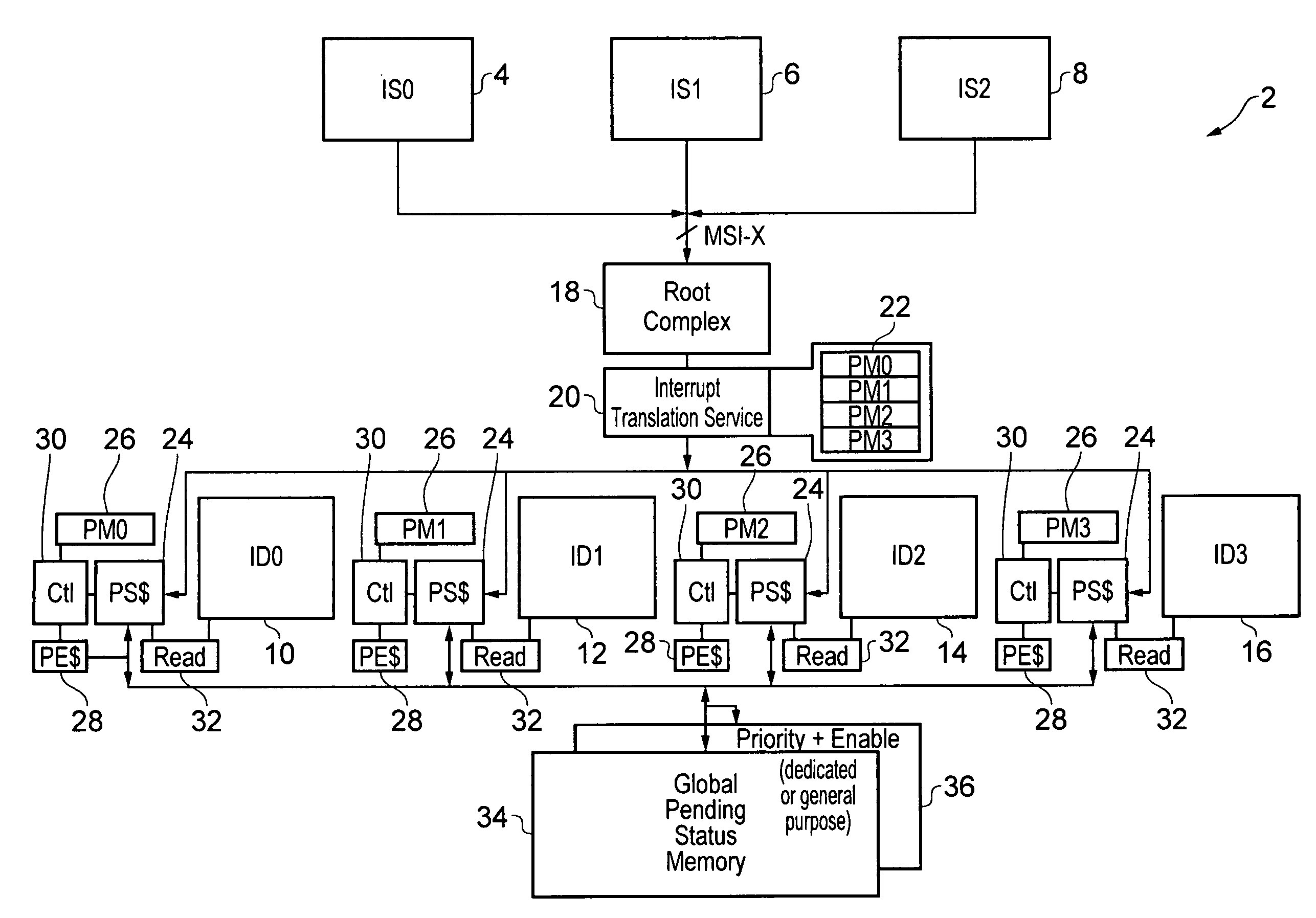
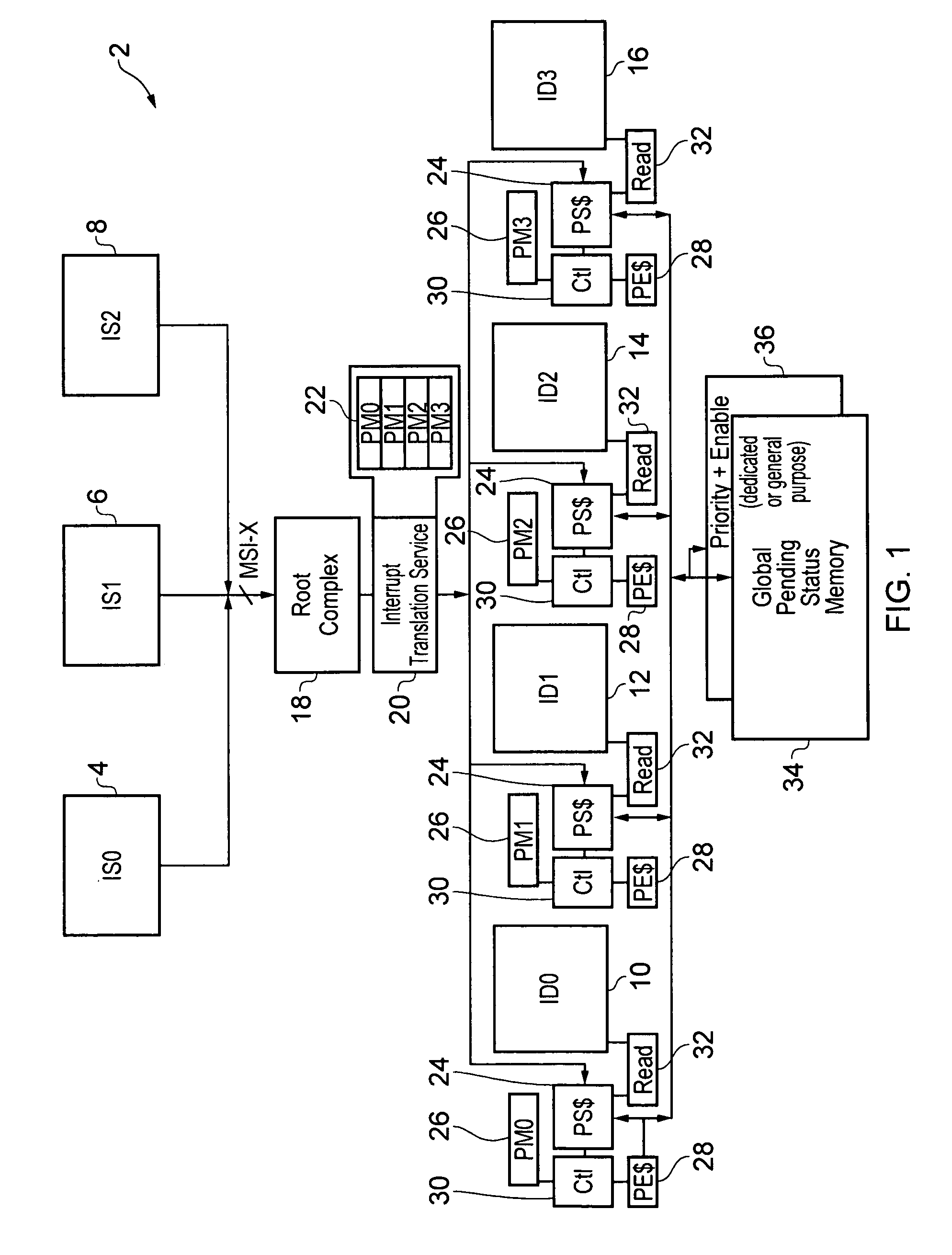
[0040]FIG. 1 schematically illustrates a data processing system 2 incorporating a plurality of data interrupt sources 4, 6, 8 and a plurality of interrupt destinations 10, 12, 14, 16. The interrupt destinations may typically be different processors within a multiprocessor system. These individual processors may be dynamically powered up and powered down depending upon the processing workload. When a processor is powered down, then any pending interrupts for that processor need to be reassigned to another processor for servicing.

[0041]The interrupt sources 4, 6, 8 may take a variety of different forms, such as U / O devices, DMA engines and other peripheral devices. The interrupt sources 4, 6, 8 generate message signalled interrupts MSI-X which are supplied to a root complex 18. Such message signalled interrupts are, for example, known from systems supporting PCI-express. Such message signalled interrupts in themselves and the root complex 18 will not be described further herein as the...


PUM


Abstract

A global interrupt number space 38 is provided for use in message signalled interrupts. Interrupt destinations 10, 12, 14, 16 are provided with pending interrupt caches 24 with either backing storage provided by global pending status memory 34 shared by all the caches or separate individual pending status memories 56. The interrupt number space may be divided into regions with programmable mapping data being used to indicate which interrupt destinations are responsible for which regions. When interrupts are migrated from one interrupt destination to another, then such programmable mapping data is updated. Pending interrupts may be flushed back to the global pending status memory 34 during the reassignment process such that this pending interrupt data may be picked up by the newly responsible interrupt destination.

Description

BACKGROUND OF THE INVENTION[0001]1. Field of the Invention[0002]This invention relates to the field of data processing systems. More particularly, this invention relates to the communication of message signalled interrupts between one or more interrupt sources and a plurality of interrupt destinations.[0003]2. Description of the Prior Art[0004]It is known to provide communication mechanisms which support message signalled interrupts passed between one or more interrupts sources, (e.g. devices within a computer system) and a plurality of interrupt destinations (e.g. processors for processing those interrupts). It is possible that each individual interrupt destination may be formed so as to be responsive to a hundred or more different interrupts with respective interrupt numbers. The message signalled interrupt contains an address of the interrupt destination and an interrupt number at that interrupt destination. Providing such a large number of interrupt numbers allows information to...

Claims


Application Information

Patent Timeline
IPC IPC(8): G06F13/26
CPCG06F13/26G06F13/24G06F9/4812G06F15/177G06F1/3287
Inventor GRISENTHWAITE, RICHARD ROYJEBSON, ANTHONYROSE, ANDREW CHRISTOPHEREVANS, MATTHEW LUCIEN
Owner ARM LTD
Why Eureka
Try Eureka