
Method for forming a heating element for use with a steering wheel

a technology for steering wheels and heating elements, applied in ohmic-resistance heating, transportation and packaging, resistive material coatings, etc., can solve problems such as affecting the driver, safety-related problems, and difficulty in arranging thin heating coils, so as to minimize heat loss and stably hold the rim

Inactive Publication Date: 2014-05-08
HWAJIN
View PDF4 Cites 0 Cited by
  • Summary
  • Abstract
  • Description
  • Claims
  • Application Information

AI Technical Summary

Benefits of technology

The present invention provides a steering wheel with a heating element that can make the driver feel more comfortable by heating the entire surface of the rim to a uniform temperature. Additionally, the heating element is made more efficient by using a conductive paste and transfer film for printing decoration patterns, which minimizes heat loss and allows for a thinner rim design. This makes it easier for the driver to hold the rim stably, improving overall comfort and safety.

Problems solved by technology

In particular, when starting to drive a vehicle in winter, a temperature of a steering wheel is lower than that of a human body, which affects the driver and might pose a safety-related problem.
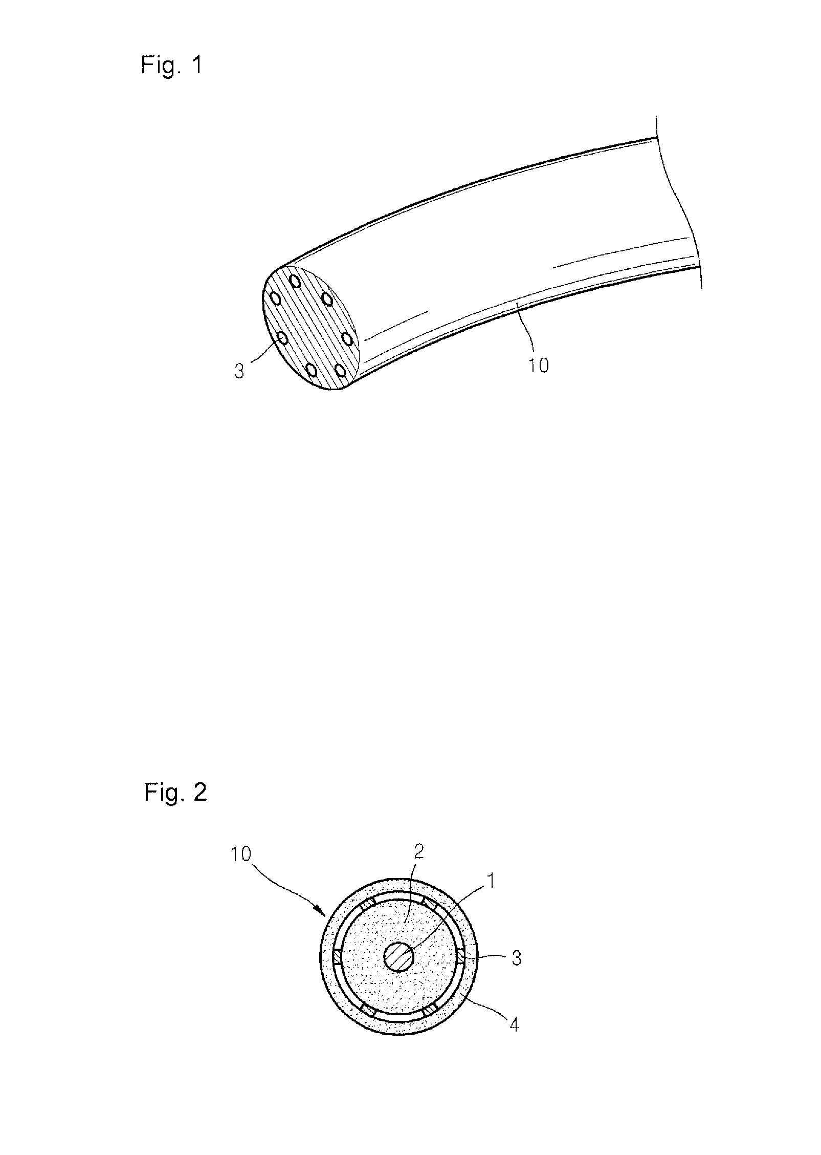
However, as shown in FIG. 2, when the heating coils 3 are fixed around the outer circumferential surface of the insulating covering material 2, it is quite difficult to arrange the thin heating coils 3 at uniform intervals in a working process, and a temperature deviation between areas in the rim portion 10 occurs in practice due to irregular distances between the heating coils 3.
In this case, the manufacture of the steering wheel is time-consuming, and thus, expensive.
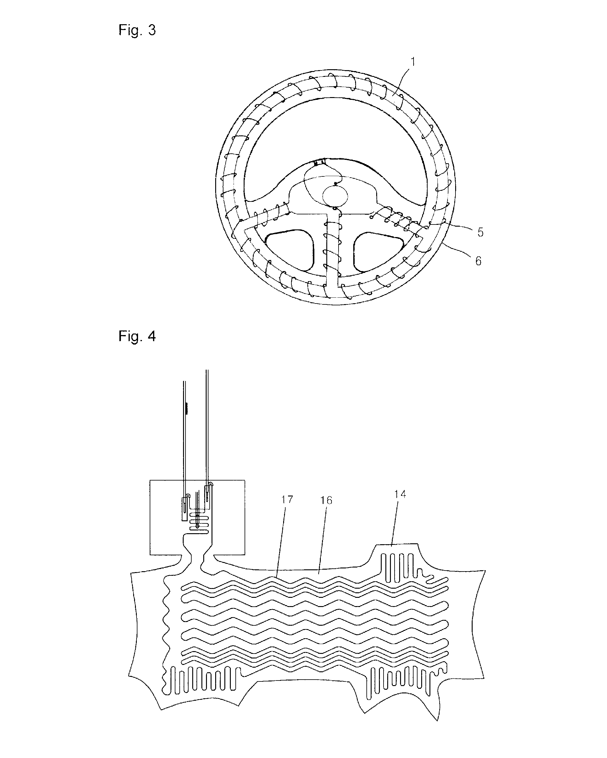
Also, due to the low thermal conductivity of the wood piece 20, the overall thermal conductivity of the steering wheel is reduced, and accordingly, heat of the plane heater 14 may not be efficiently utilized.

Method used


Image

  • Method for forming a heating element for use with a steering wheel
  • Method for forming a heating element for use with a steering wheel
  • Method for forming a heating element for use with a steering wheel

Examples


Embodiment Construction

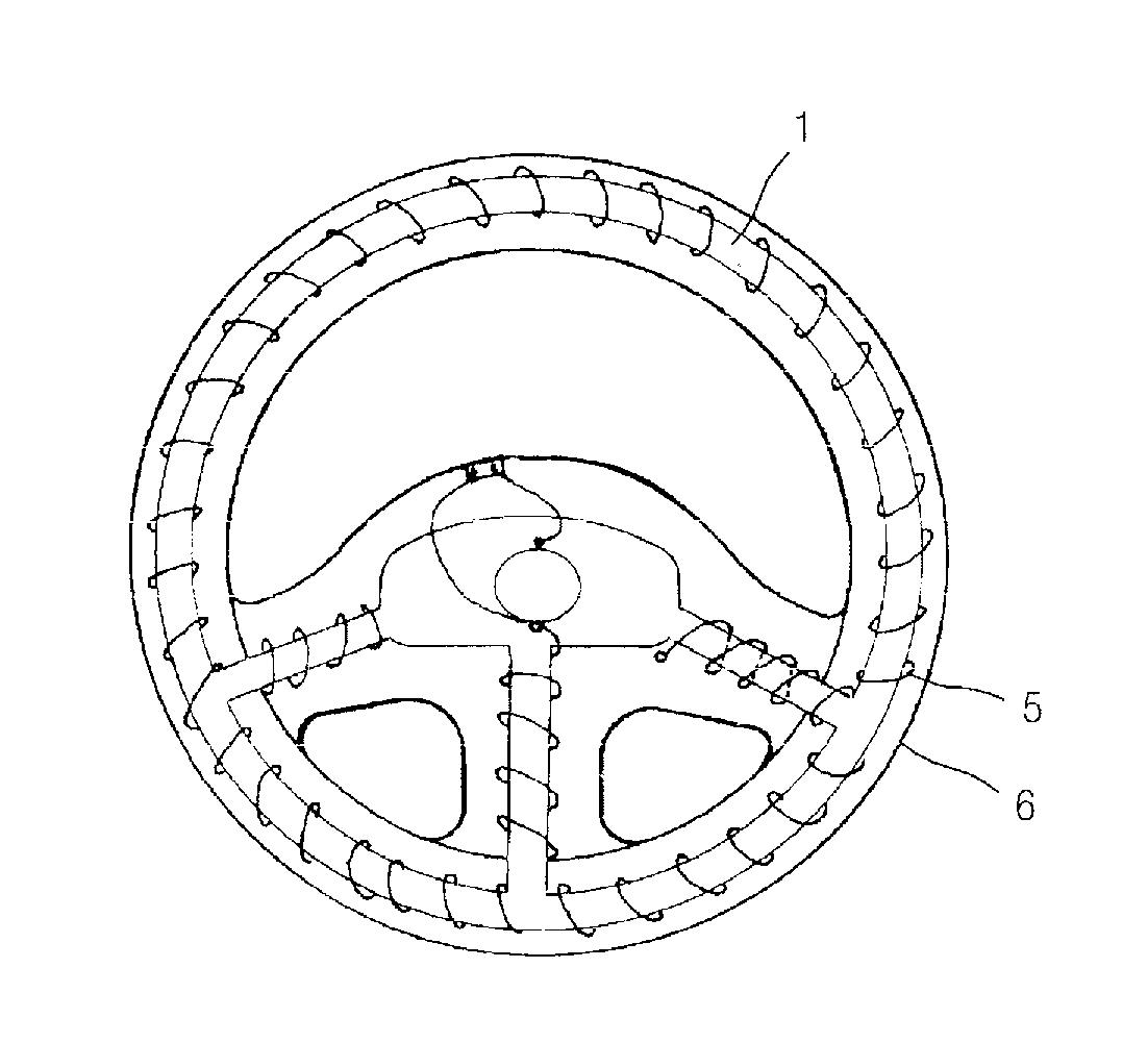
[0034]The present invention provides a steering wheel including a heating element which may minimize a temperature deviation felt by a driver by heating an entire surface of a rim to a uniform temperature. The present invention also provides a steering wheel including a heating element which may continuously generate heat in other portions even though a portion of the heating element is electrically disconnected. The present invention also provides a steering wheel including a heating element which may transfer a transfer film, on which a decoration pattern is printed, onto a surface of the heating element.

[0035]According to an aspect of the present invention, there is provided a steering wheel comprising a rim, and a heating element coated on a surface of the rim, the heating element being heated by power supply, wherein the heating element is an electrically conductive paste, and comprises a first heating part which is coated in a longitudinal direction of the rim along an inner d...


PUM

PropertyMeasurementUnit
temperatureaaaaaaaaaa
inner diameteraaaaaaaaaa
outer diameteraaaaaaaaaa

Abstract

A method of forming a heating element for use with a steering wheel includes (i) forming a first heating part of a heating element which is coated in a longitudinal direction of the rim along an inner diameter portion of the rim by continuously connecting loops having the same shape, (ii) forming a second heating part of the heating element which is coated in the longitudinal direction of the rim along an outer diameter portion of the rim by continuously connecting loops having the same shape, (iii) forming a third heating part of the heating element which is coated in the longitudinal direction of the rim by continuously connecting loops having the same shape between the first heating part and the second heating part; and (iv) adjusting an electrical resistance of the heating element according to a coating width or thickness of the conductive paste.

Description

PRIORITY[0001]This application is a divisional of application Ser. No. 13 / 867,276, filed Apr. 22, 2013 and entitled Steering Wheel Including Heating Element. Application Ser. No. 13 / 867,276 is a continuation of Patent Cooperation Treaty (PCT) international application Serial No. PCT / KR2011 / 002166, filed on Mar. 30, 2011 and which designates the United States, which claims priority to Korean Patent Application No. 10-2010-0102514, filed on Oct. 20, 2010. The entirety of both Patent Cooperation Treaty (PCT) international application Serial No. PCT / KR2011 / 002166 and Korean Patent Application No. 10-2010-0102514 are hereby incorporated by reference herein.BACKGROUND OF THE INVENTION[0002]1. Technical Field[0003]The present invention relates to a steering wheel including a heating element, and more particularly, to a steering wheel including a heating element which may minimize a temperature deviation felt by a driver by heating an entire surface of a rim to a uniform temperature. The pr...

Claims


Application Information

Patent Timeline
Patent Type & Authority Applications(United States)
IPC IPC(8): B62D1/06H01C17/06
CPCH01C17/06B62D1/065H05B3/36H05B2203/014Y10T29/49083Y10T29/49099B62D1/06H01C17/02
Inventor CHO, MAN HO
Owner HWAJIN
Learn More