

Physical quantity detecting device, electronic apparatus, and moving object
- Summary
- Abstract
- Description
- Claims
- Application Information
AI Technical Summary
Benefits of technology
Problems solved by technology
Method used
Image

Examples
first embodiment
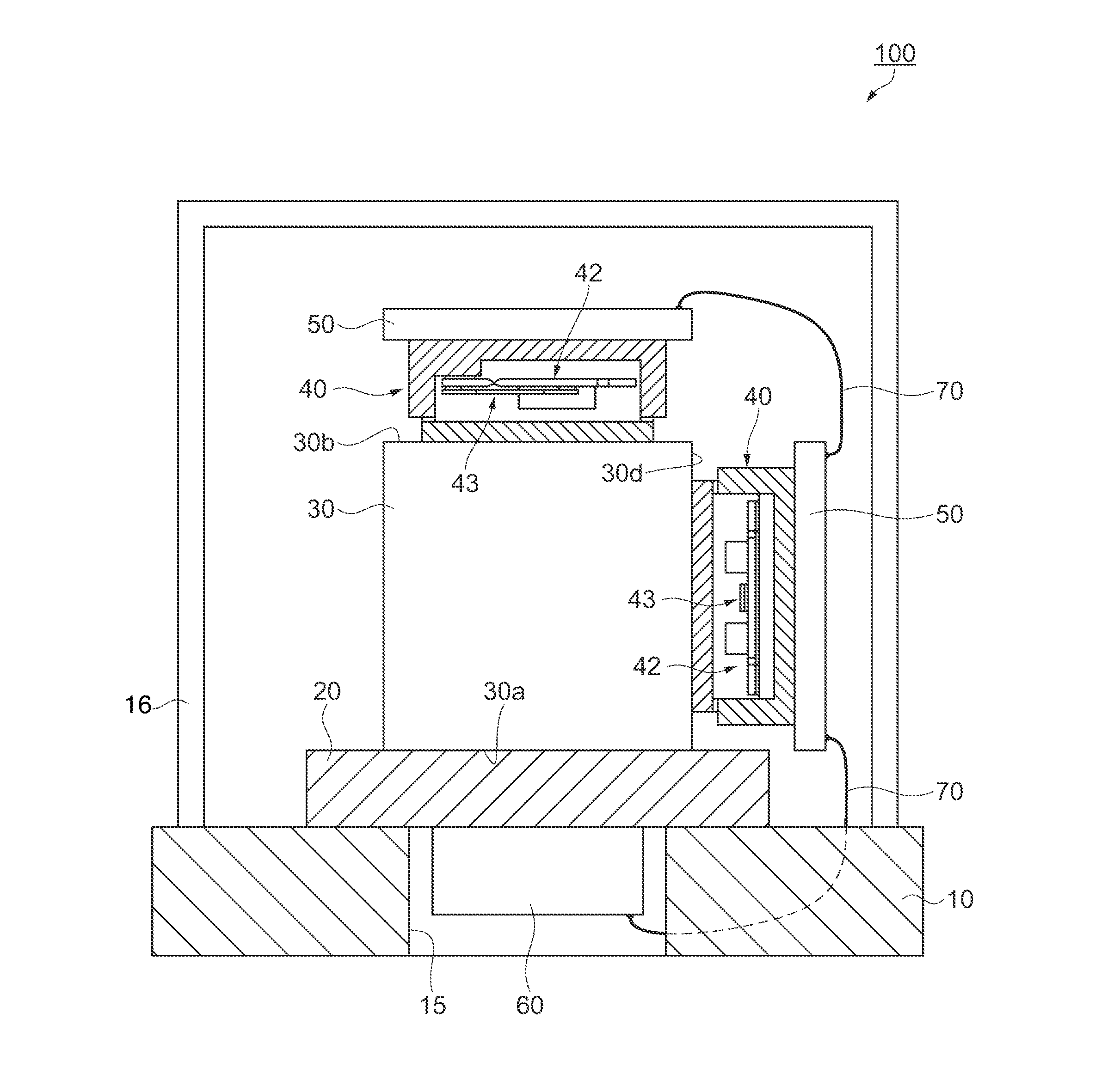
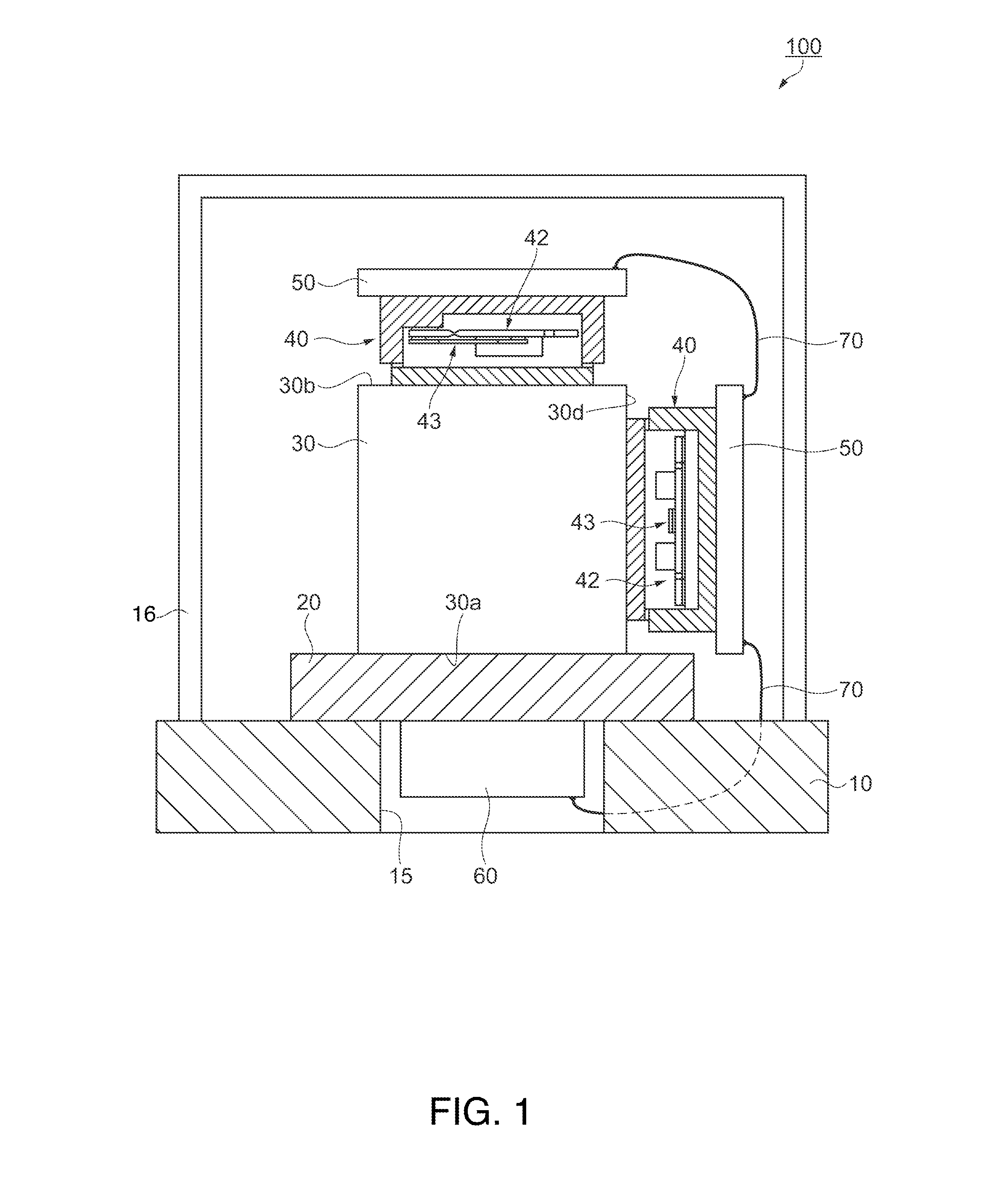
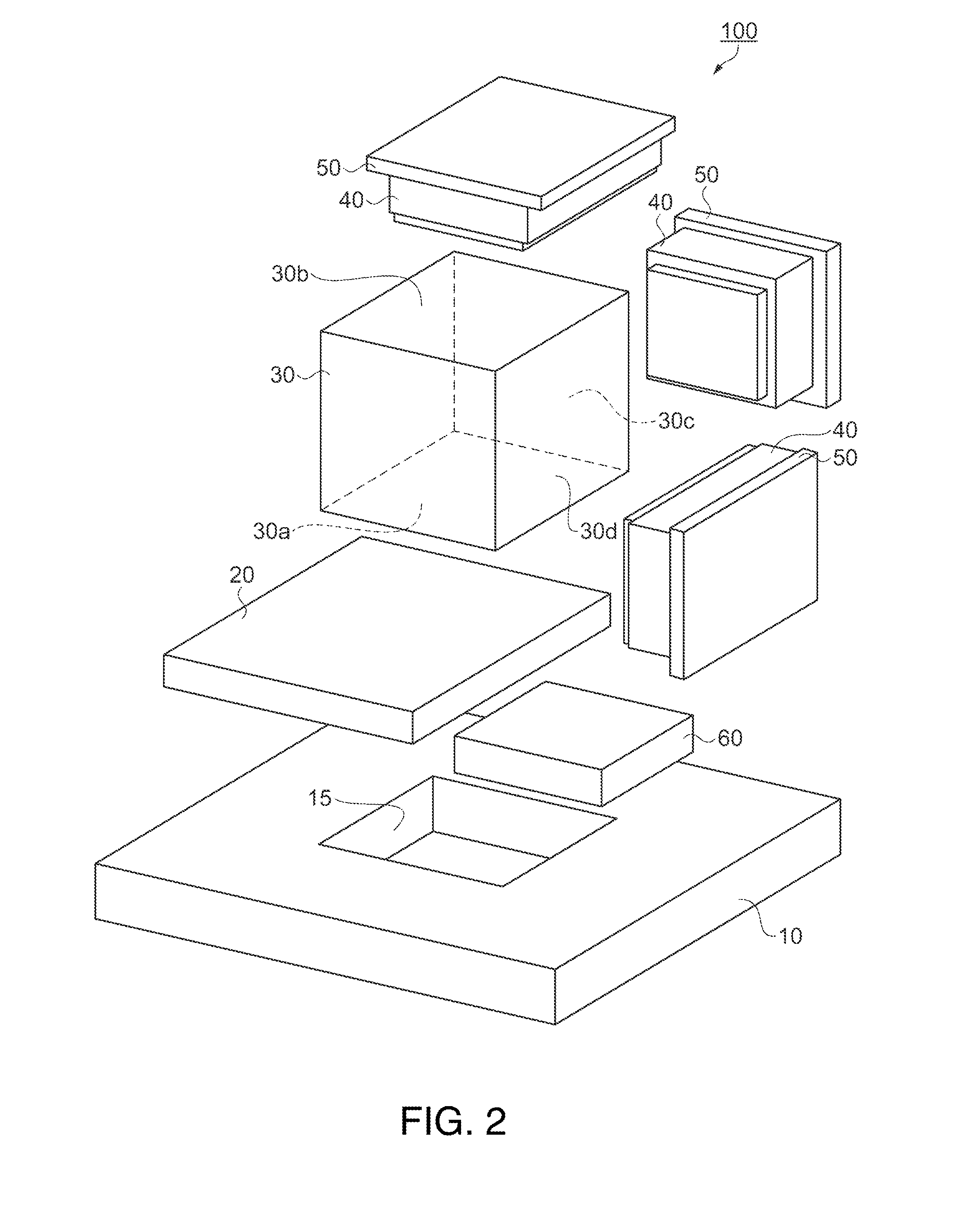
[0044]As shown in FIGS. 1 and 2, a physical quantity detecting device 100 includes a circuit board 10 including an opening section 15, which is a square through-hole, a heat insulating material (a heat-conduction reducing section) 20 arranged on one surface side of the circuit board 10 and covering the opening section 15, a cube-shaped metal block (a holding section) 30 arranged such that a lower surface 30a thereof is fixed to the surface of the heat insulating material 20 on the opposite side of the circuit board 10, inclination detectors 40, which are physical quantity detectors, respectively arranged on an upper surface 30b opposed to the lower surface 30a of the metal block 30 and side surfaces 30c and 30d adjacent to the lower surface 30a, oscillation circuit boards 50 respectively provided in the inclination detectors 40 and for driving the inclination detectors 40, an electronic component 60 provided in the heat insulating material 20 to be housed on the inside of the openin...
second modification
[0062]Another preferred example in the physical quantity detecting device 100 is explained. FIG. 5 is a sectional view showing the configuration of a physical quantity detecting device according to a second embodiment of the invention. A physical quantity detecting device 200 in the second embodiment is different from the physical quantity detecting device 100 in the first embodiment in the circuit board 10 and an opening section 15a. Therefore, sections other than the different sections are denoted by numerals and signs same as those in the first embodiment and explained.
[0063]As shown in FIG. 5, the physical quantity detecting device 200 includes the circuit board 10, the heat insulating material 20 arranged on one surface side of the circuit board 10, the cube-shaped metal block 30 arranged such that the lower surface 30a thereof is fixed to the surface of the heat insulating material 20 on the opposite side of the circuit board 10, the inclination detectors 40 respectively arran...
third embodiment
[0068]Another preferred example in the physical quantity detecting device 100 is explained. FIG. 7 is a sectional view showing the configuration of a physical quantity detecting device according to a third embodiment of the invention. A physical quantity detecting device 300 in the third embodiment has characteristics in setting of respective surfaces on which the metal block 30 and the heat insulating material 20 and the inclination detectors 40 are connected and a connection structure of the heat insulating material 20 and the metal block 30. The characteristic sections are different from the characteristic sections of the physical quantity detecting device 100 in the first embodiment. Therefore, sections other than the sections different from those in the first embodiment are denoted by the same reference numerals and signs and explanation of the sections is omitted.
[0069]As shown in FIG. 7, the physical quantity detecting device 300 includes the circuit board 10 including the op...
PUM
 Abstract
Description
Claims
Application Information