Vertical take-off and landing aircraft with tiltrotor power for use on land and in air

a technology of vertical take-off and landing and tilting, which is applied in the direction of vertical landing/take-off aircraft, aircraft navigation control, transportation and packaging, etc., can solve the problems of difficult manufacturing, difficult to observe the conditions ahead of the flying car, and hurting people, so as to achieve safe operation of the aircraft, wide vision, and convenient conversion

Active Publication Date: 2014-05-08
YANG ZHAOXI
View PDF3 Cites 46 Cited by
  • Summary
  • Abstract
  • Description
  • Claims
  • Application Information

AI Technical Summary

Benefits of technology

[0018]By controlling the tilting angle of the thrusters arranged in front and back of the body, the aircraft for use on land and in the air according to the present invention has two basic functions of vertical takeoff/landing and horizontal flight, and realizes convenient conversion between land travel and air flight. During flight in the air, the body of the aircraft always remains in horizontal state, thereby making the occupants feel comfortable and providing them with broad vision so as to operate the aircraft safely. The aircraft for use on land and in the air according to the present invention has the advantages of simple structure, convenient operation and control, and occupying less area on the ground and being easy to travel on the ground.
[0019]The invention has the following advantages: 1. the front and rear thrusters can maintain in balance without external force, when the aircraft is on the ground, hovering, and p...

Problems solved by technology

This kind of flying car has the following disadvantages: firstly, the flying car cannot take off and land vertically; secondly, high-speed rotating of the propellers might hurt persons when the flying car operates on the ground; thirdly, the flying car has a complex structure with too many moving parts, ...

Method used


Image

  • Vertical take-off and landing aircraft with tiltrotor power for use on land and in air
  • Vertical take-off and landing aircraft with tiltrotor power for use on land and in air
  • Vertical take-off and landing aircraft with tiltrotor power for use on land and in air

Examples


example 1

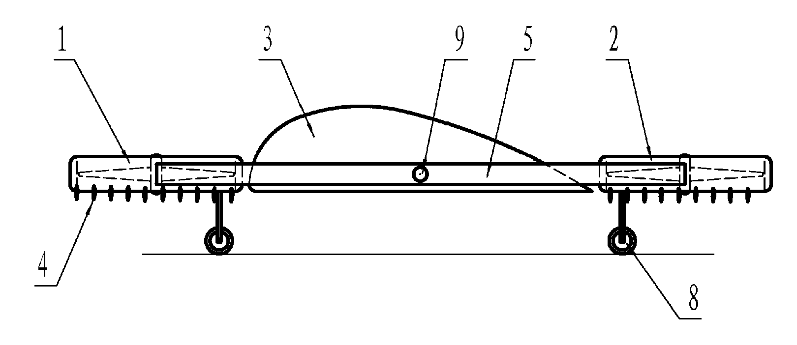
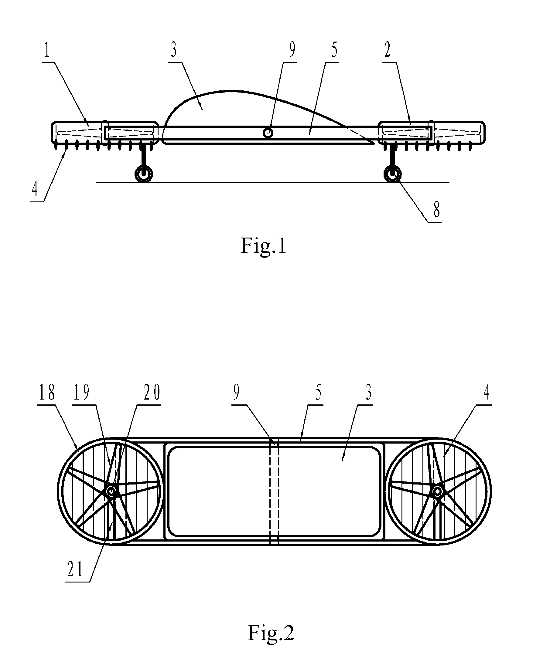
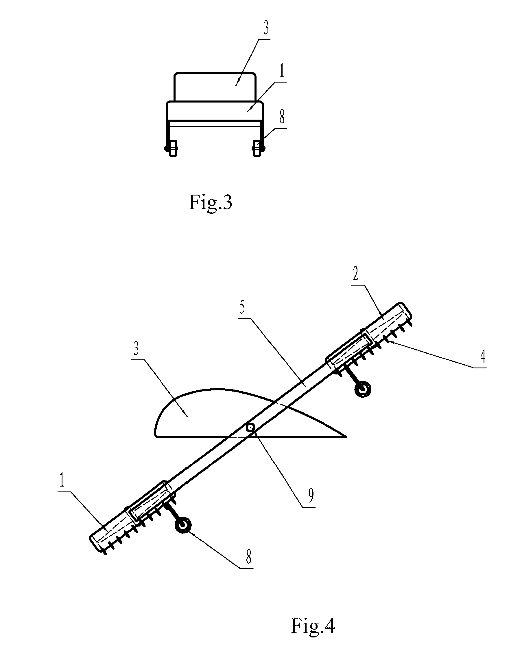
[0043]As shown in FIGS. 1-3, the present aircraft has a body 3, which is designed in accordance with the principles of aerodynamics, and in which an autopilot, a drive device, and a pivot rotation controller (or “tilting mechanism”), etc. can be installed. A first pivot 9 passes transversely through the middle portion of the body 3 with both ends of the first pivot extending out of the body 3. The two ends are connected with transmission brace rods 5 arranged on both sides of the body respectively, and the connecting points are located at the middle point of the transmission brace rods (FIG. 1). This allows keeping front and rear thrusters in balance when the front and the rear thrusters and the body are not subject to external forces. The two transmission brace rods 5 are parallel to each other, and perpendicularly connected to a first pivot 9, thereby constituting an “H”-shaped carrying-sedan structure (FIG. 2).

[0044]Between the front ends of the two transmission brace rods 5 is f...

example 2

[0050]As shown in FIG. 6 and FIG. 7, the aircraft in this example is substantially the same as that in Example 1, except that the first pivot 9 passing transversely through the tail portion of the body 3 and is connected to the rear segments of the transmission brace rods 5. Accordingly, between the body 3 and the transmission brace rods 5 is installed a deflection control mechanism 6 controlling the deflection of the transmission brace rods 5. Via the deflection control mechanism 6, the transmission brace rods 5 may be driven to rotate in the range of 0-90°, so that the front thruster 1 is tilted downwards and the rear thruster 2 is tilted upwards. The deflection control mechanism 6 may comprise a hydraulic cylinder or pneumatic cylinder and other mechanical device.

example 3

[0051]As shown in FIG. 8 and FIG. 9, the aircraft in this example is substantially the same as that in Example 1, except that the aircraft is further provided with two lateral thrusters 16, and the wheels 8 are installed on the bottom of the body 3.

[0052]In FIG. 9, the two ends of the first pivot 9 extend transversely out of the middle portion of the body 3, firstly are connected with the transmission brace rods 5 on the two sides of the body 9, and then each are connected externally to one lateral thruster 16. Thus, the aircraft is provided with ducted fans in the front, rear, left and right directions of the body 3. The two lateral thrusters 16 are tilted by the first pivot 9, and the lateral thrusters 16 on the one hand and the front thruster 1 and the rear thruster 2 connected to the transmission brace rods 5 on the other hand may be tilted synchronously or asynchronously.

[0053]Due to the increased thrust forces, this aircraft can carry increased load and its flight stability an...


PUM


Abstract

A vertical take-off and landing aircraft with tiltable power for use on land and in the air includes: a body (3) provided with a drive device; wheels (8) being controlled to make the body move on the ground; and a front thruster (1) and a rear thruster (2) controlling the body to fly or take off/land, wherein transmission brace rods (5) are arranged on both sides of the body, and a first pivot (9) passes transversely through the body and is connected to the transmission brace rods on both sides of the body; wherein the front thruster is fixed on front ends of the transmission brace rods, and the rear thruster is fixed on rear ends of the transmission brace rods; wherein the central axes of the front and rear thrusters are perpendicular to the plane formed by the two transmission brace rods. By controlling a tilting angle of the front/rear thrusters, this aircraft has two basic functions of vertical take-off/landing and horizontal flight, so as to facilitate conversion between land travel and air flight. During flight in the air, the aircraft body always remains in horizontal state, thereby making the occupants feel comfortable and providing them with broad vision so as to operate the aircraft safely.

Description

TECHNICAL FIELD[0001]This invention relates to a small aircraft, and in particular, to a vertical take-off and landing aircraft with tiltable power for use on land and in air.BACKGROUND ART[0002]U.S. Pat. No. 3,090,581 discloses a flying car, wherein the flying car is provided at the front and rear portions of its body with a respective tiltable propeller, which can be stowed in the body.[0003]When the flying car is flying in the air, the front and rear propellers are open with its propeller shaft horizontal, so that the propellers can generate a backward thrust force. When the thrust force is increased to a certain degree, the flying car will be ready to fly. This kind of flying car has the following disadvantages: firstly, the flying car cannot take off and land vertically; secondly, high-speed rotating of the propellers might hurt persons when the flying car operates on the ground; thirdly, the flying car has a complex structure with too many moving parts, and thus is difficult t...

Claims


Application Information

Patent Timeline
IPC IPC(8): B64C37/00B64C29/00
CPCB64C29/00B64C37/00B64C3/546B64C29/0033B64C39/04
Inventor YANG, ZHAOXI
Owner YANG ZHAOXI
Why Eureka
Try Eureka