Fishing adapter

a technology for adapters and fish, applied in the direction of propulsion, cable installation apparatus, pipe-laying vessels, etc., can solve the problems of insufficient security, bit tip, inconvenient assembly, etc., and achieve the effect of simplifying the manufacture of the device and convenient and reliable security

a technology for adapters and fish, applied in the direction of propulsion, cable installation apparatus, pipe-laying vessels, etc., can solve the problems of insufficient security, bit tip, inconvenient assembly, etc., and achieve the effect of simplifying the manufacture of the device and convenient and reliable security

US20140124717A1Active Publication Date: 2014-05-08MALTBY MALORY

Image

  • Fishing adapter
  • Fishing adapter
  • Fishing adapter

Examples


Embodiment Construction

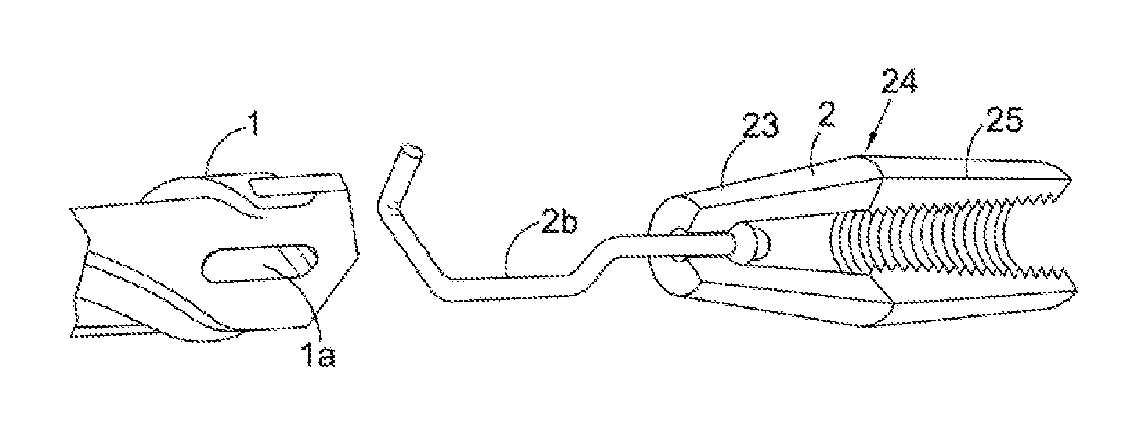
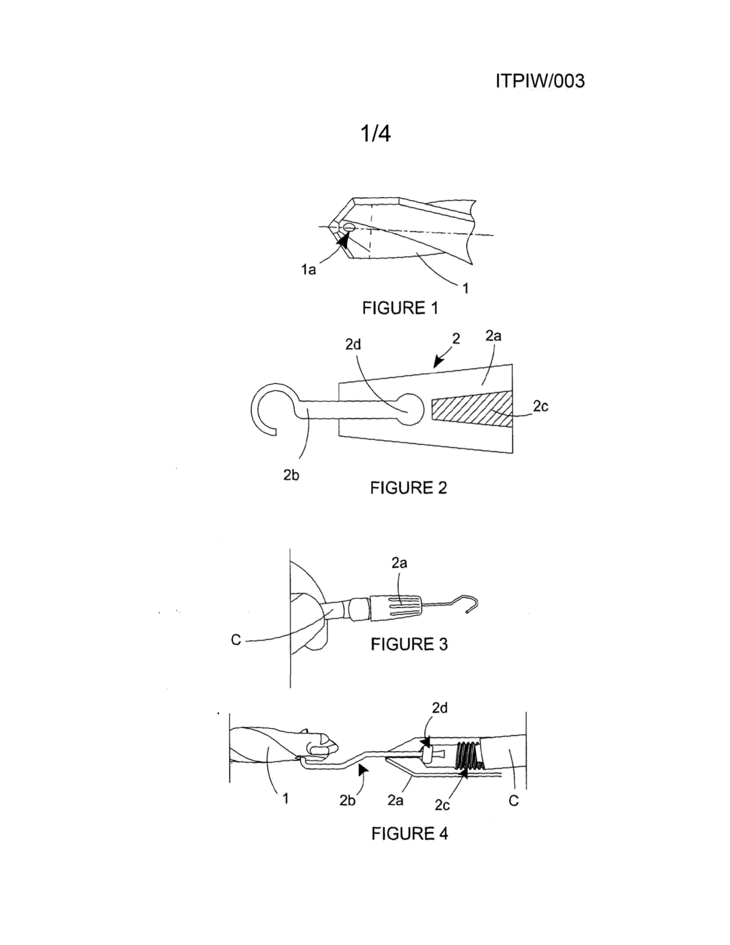
[0026]Referring to FIG. 1, this illustrates a drill bit 1 modified to have a hole 1a in the end of the drill bit 1 close to the cutting tip and orthogonal to the longitudinal axis of the bit 1. The hole 1a is elliptical / elongate in the axial direction of the drill bit 1 as can be seen. This enables a hook to be inserted though the hole 1a, by insertion into the hole 1a from one side and turning the hook until the stem / shank of the hook is substantially oriented in the axial direction of the drill bit 1 to be secure in place for pulling behind the drill bit 1 as the drill bit 1 is retracted back through a hole drilled through a wall.

[0027]The drill bit 1 may be formed with the hole 1a during the manufacture of the bit 1, and in the case of spade or masonry drill bits, may be provided within the tungsten cutting part prior to that part being brazed in place. A hole may also be made in an existing drill bit with the use of a water jet cutter or plasma cutter. Preferably heat-producing ...


PUM


Abstract

The present invention concerns fishing adapters for pilling a cable or the like through a hole drilled in a wall or other structure and in one aspect comprises a drill bit connector to enable the adapter to be demountably attached to a drill bit and an item connector to enable a cable or other elongate / linear item to be attached to the adapter, wherein the adapter further has a rotary coupling between the drill bit connector and the item connector to permit the drill bit to rotate as the adapter with cable or other elongate / linear item attached is pulled through a drilled hole without significantly twisting said cable or other elongate / linear item.

Description

FIELD OF THE INVENTION[0001]The present invention concerns a fishing adapter, also known as a ‘wire fishing adapter’, being a device to connect a length of an item such as wire or cable (or in our case also pipe / conduit or other elongate / linear items) to a drill bit that has penetrated through a wail or other structure for pulling (a.k.a. ‘fishing’) the item back through the wall / structure when retracting the drill bit. In most cases the elongate / linear items to be ‘fished’ are, like wire and cable, not rigidly rectilinear but liable to bend and, therefore, difficult to push through a wall or other solid / semisolid structure and thus need to be pulled through.BACKGROUND TO THE INVENTION[0002]Fishing adapters of the type in question are used by workmen passing flexible electrical wire or cables through masonry, concrete or timber walls or through other solid or semi-solid structures / media. Fishing adapters are designed to help to reduce the time needed to install the wire or cables. A...

Claims


Application Information

Patent Timeline
08 May 2014
Publication
US20140124717A1
IPC
H02G1/08
CPC
H02G1/083
Inventors
MALTBY, MALORY