Self-oscillation circuit

a self-oscillation circuit and circuit technology, applied in the direction of oscillating generators, electrical equipment, etc., can solve the problems of not revealing any method, not revealing any technique for obtaining a stable oscillation frequency, and difficult to have a smaller drive current for oscillating crystal resonators than the drive withstand curren

Inactive Publication Date: 2014-05-08
NIHON DEMPA KOGYO CO LTD
View PDF5 Cites 7 Cited by
  • Summary
  • Abstract
  • Description
  • Claims
  • Application Information

AI Technical Summary

Benefits of technology

[0003]An oscillation circuit that includes a crystal resonator is utilized widely in the information communication field. Further reduction in size, reduction in electric power, and high frequency stability are required for this oscillation circuit. Typically, as the crystal resonator is reduced in size, the upper limit (drive withstand current) of drive current for stable operation is known to be decreased. On the other hand, considering stability in oscillation frequency against electronic noise and temperature change, it may be difficult to have a smaller drive current for oscillating the crystal resonator than the drive withstand current.

Problems solved by technology

On the other hand, considering stability in oscillation frequency against electronic noise and temperature change, it may be difficult to have a smaller drive current for oscillating the crystal resonator than the drive withstand current.
However, Patent Literature 1 does not disclose any method for solving the above-described problem occurring when the drive current supplied to the piezoelectric resonator is decreased.
Similarly, Patent Literature 2 does not disclose any technique for obtaining a stable oscillation frequency while decreasing the drive current.

Method used


Image

  • Self-oscillation circuit
  • Self-oscillation circuit
  • Self-oscillation circuit

Examples


working example

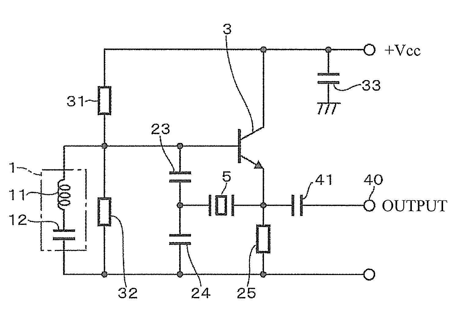
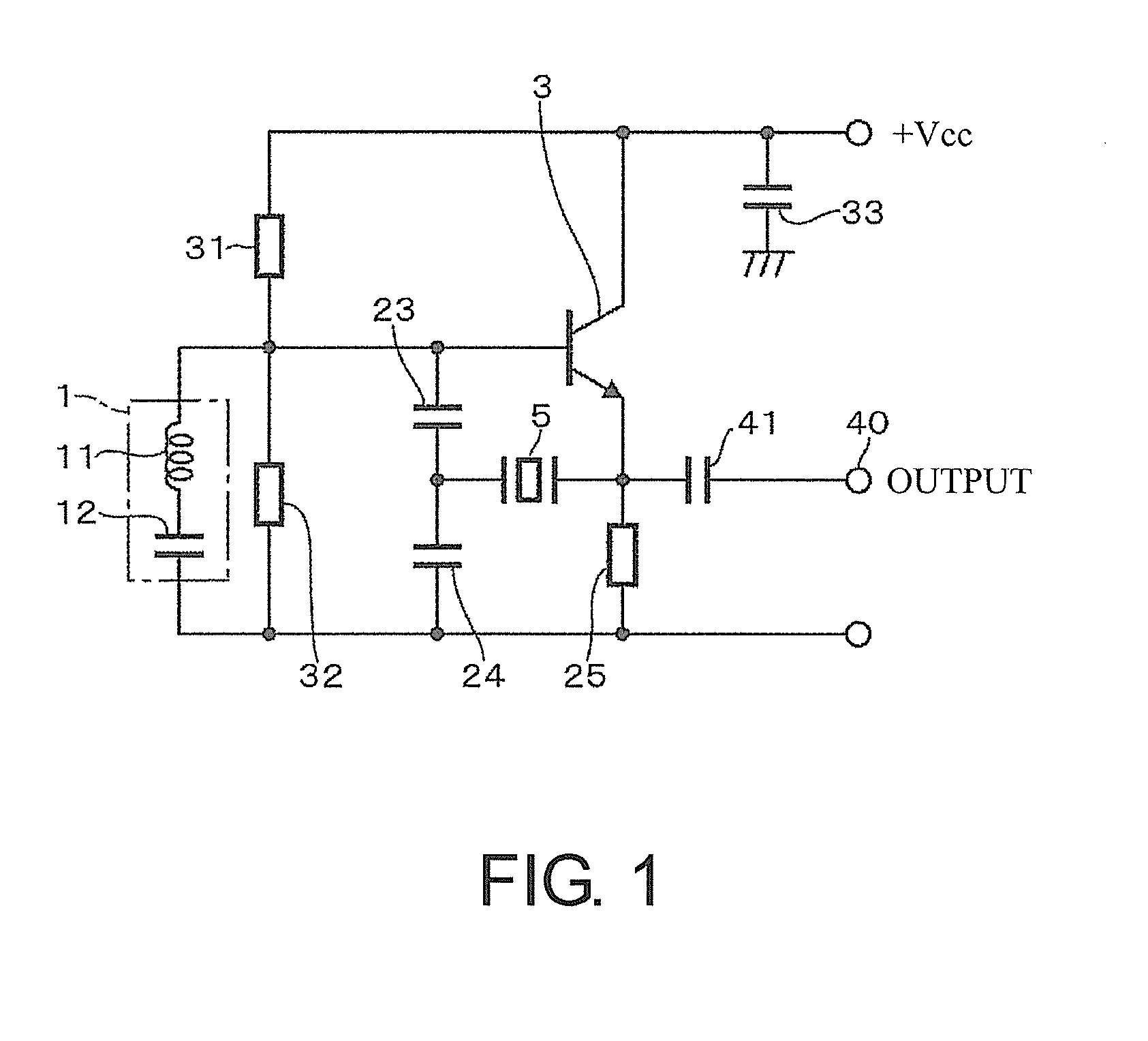
[0053]The self-oscillation circuit in FIG. 1 where the oscillating unit 1 was constituted of the LC oscillation circuit and the crystal resonator 5 was disposed in the oscillation loop was oscillated under the temperature condition of −30° C. to +85° C., so as to measure a frequency versus temperature characteristic. The oscillation frequency of the oscillating unit 1 was 26.0 MHz, the drive current was 0.26 mA, and the crystal resonator 5 employed an AT-cut crystal resonator with a resonant frequency of 26.0 MHz. The load capacitance component at an active circuit side viewed from the crystal resonator 5 (at a circuit side that includes the oscillating unit 1, the bleeder resistors 31 and 32, and the voltage-dividing capacitors 23 and 24) coincided with that of a comparative example. The frequency was measured based on the international standard (IEC 60444-7).


PUM


Abstract

A self-oscillation circuit includes an oscillating unit, an amplifying unit, and a resonator. The oscillating unit is configured to self-oscillate. The amplifying unit is configured to amplify a frequency signal oscillated at the oscillating unit and to feed back the amplified frequency signal to the oscillating unit. The resonator is disposed in an oscillation loop that includes the oscillating unit and the amplifying unit. The resonator has a resonant frequency near an oscillation frequency of the oscillating unit and has a higher Q-value than a Q-value of the oscillating unit.

Description

CROSS REFERENCE TO RELATED APPLICATIONS[0001]This application claims the priority benefit of Japan application serial no. 2012-245518, filed on Nov. 7, 2012. The entirety of the above-mentioned patent application is hereby incorporated by reference herein and made a part of this specification.TECHNICAL FIELD[0002]This disclosure relates to a self-oscillation circuit with an oscillating unit that self-oscillates.DESCRIPTION OF THE RELATED ART[0003]An oscillation circuit that includes a crystal resonator is utilized widely in the information communication field. Further reduction in size, reduction in electric power, and high frequency stability are required for this oscillation circuit. Typically, as the crystal resonator is reduced in size, the upper limit (drive withstand current) of drive current for stable operation is known to be decreased. On the other hand, considering stability in oscillation frequency against electronic noise and temperature change, it may be difficult to ha...

Claims


Application Information

Patent Timeline
Patent Type & Authority Applications(United States)
IPC IPC(8): H03B5/36
CPCH03B5/362H03B5/326H03B2201/02
Inventor KOYAMA, MITSUAKIMUTOH, TAKERUISHIKAWA, MANABU
Owner NIHON DEMPA KOGYO CO LTD
Why Eureka
Try Eureka