
Transportation device and recording apparatus

a technology of transporting device and recording device, which is applied in the direction of electrical equipment, thin material processing, printing, etc., can solve the problems of degrading the imaging accuracy of recording paper and the extension of the lens barrel, and achieve the effect of the same operation advantag

Active Publication Date: 2014-05-08
SEIKO EPSON CORP
View PDF8 Cites 4 Cited by
  • Summary
  • Abstract
  • Description
  • Claims
  • Application Information

AI Technical Summary

Benefits of technology

The invention provides a transportation device and recording apparatus that can maintain accurate detection of objects even when the ambient temperature increases. By extending the case and moving the optical member and imaging section together, the positional relationship between them is maintained, suppressing shifting of the focus position and degradation of the imaging accuracy. The members of the case can have the same coefficient of linear expansion, making it easier to conform the expansion of the device. Additionally, the invention reduces the movement of the light irradiation section and maintains the distance between it and the object being detected, preventing degradation in the irradiation accuracy. Overall, the invention provides improved performance and operational advantage.

Problems solved by technology

However, in the photographing device of the printer described above, it is not considered particularly that the lens barrel is extended by an increase in an ambient temperature thereof.
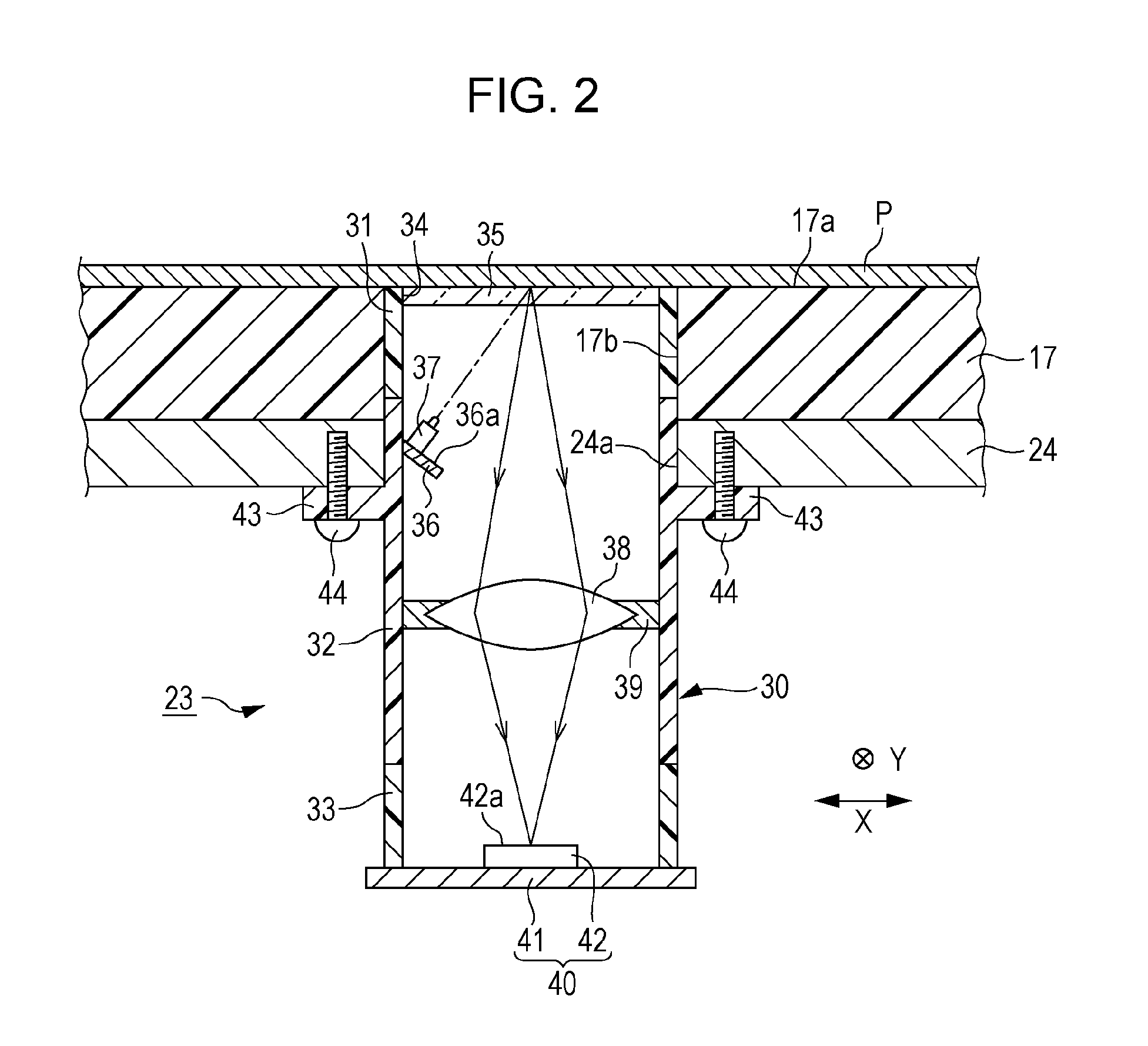
Thus, when the lens barrel is extended by the increase in the ambient temperature, since a positional relationship between the optical system and the imaging element is out of order, there is a problem that a focus position of the optical system is shifted and then imaging accuracy of the recording paper is degraded due to the imaging element.

Method used


Image

  • Transportation device and recording apparatus
  • Transportation device and recording apparatus
  • Transportation device and recording apparatus

Examples


modification example

[0057]In addition, the embodiment described above may be modified as described below.

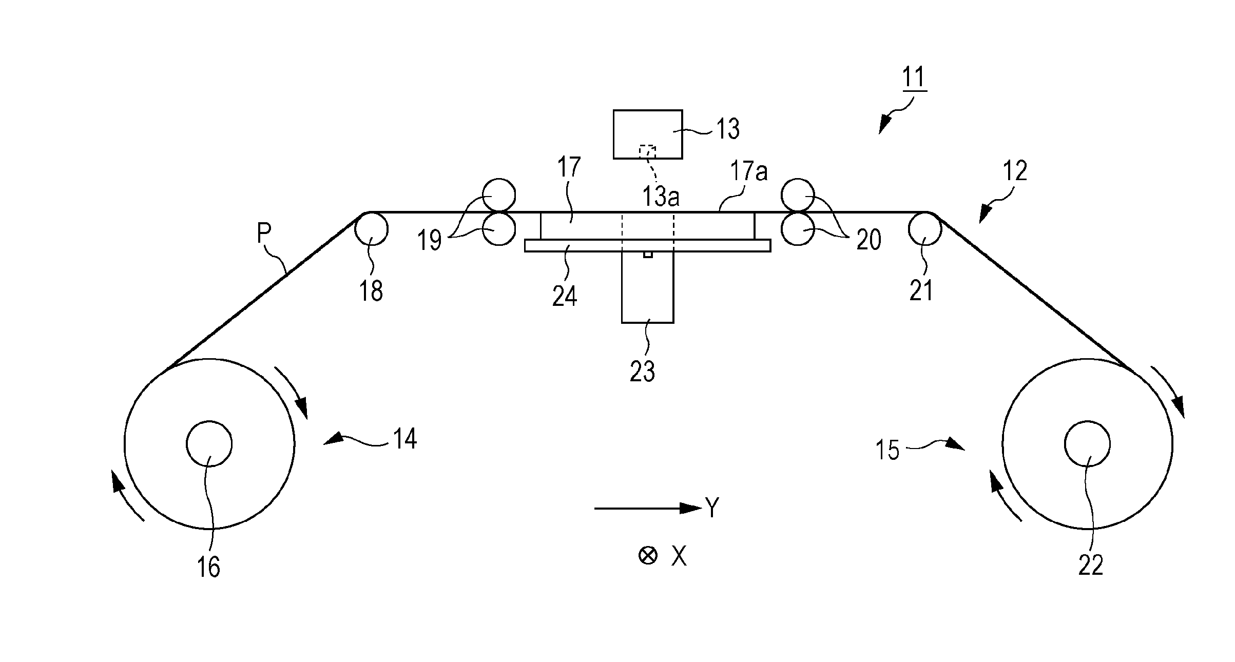
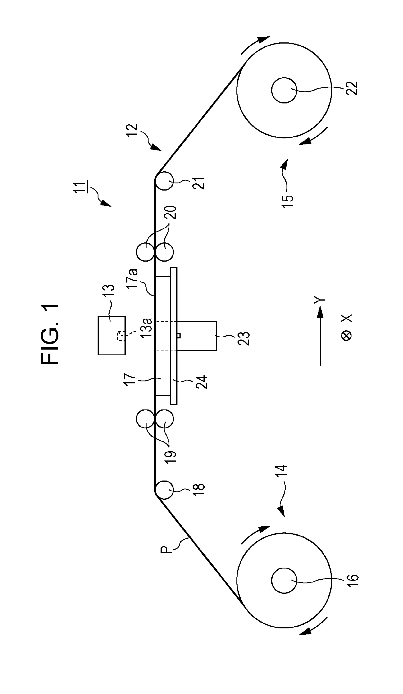
[0058]In the imaging unit 23 of the transportation device 12, the lens barrel 30 may be fixed to the support frame 24 in a position where a distance from the continuous paper P is the same as a distance between the continuous paper P and the light irradiation section 37. Thus, when the ambient temperature of the imaging unit 23 (the lens barrel 30) is increased, since the lens barrel 30 is vertically extended from the position which is fixed by the support frame 24 as the base point, it is possible to reduce the moving amount of the light irradiation section 37 depending on the extension of the lens barrel 30. Therefore, since the change in the distance between the light irradiation section 37 and the continuous paper P can be suppressed, it is possible to suppress the degradation of irradiation accuracy of the light with respect to the continuous paper P due to the light irradiation section 37.

[005...


PUM


Abstract

A transportation device includes: a transportation section that transports a continuous paper; and an imaging unit that detects a transportation amount of the continuous paper which is transported by the transportation section. The imaging unit includes a lens barrel; a light irradiation unit disposed in the lens barrel and capable of radiating light on the continuous paper; a condensing lens which is disposed in a position farther than the light irradiation section with respect to the continuous paper in the lens barrel and condenses a reflected light when the light is radiated from the light irradiation section to the continuous paper; and an imaging element which is disposed in a position farther than the condensing lens with respect to the continuous paper P in the lens barrel and captures an image by receiving the reflected light condensed by the condensing lens.

Description

BACKGROUND[0001]1. Technical Field[0002]The present invention relates to a transportation device transporting an object to be detected such as a paper which is used, for example, in printing or the like and a recording apparatus including the transportation device.[0003]2. Related Art[0004]In the related art, as a type of recording apparatus, an ink jet type printer is disclosed which forms an image by ejecting ink from a recording head (a recording section) to a recording paper (an object to be detected) (for example, JP-A-2007-217176).[0005]A printer disclosed in JP-A-2007-217176 includes a photographing device (a detection section) having a light emitting element (a light irradiation section) and an imaging element (an imaging section) which has an optical system (an optical member). Then, a surface texture of the recording paper which is transported is imaged as a continuous image by the photographing device. A moving amount of a target pattern in each image is calculated by com...

Claims


Application Information

Patent Timeline
Patent Type & Authority Applications(United States)
IPC IPC(8): B41J15/00
CPCB41J15/00B41J11/42B41J15/04H04N1/0476H04N1/1215G01N21/86B65H7/02B65H7/00B41J13/0009B41J11/0095H04N1/23H04N1/00838
Inventor ABE, TAKAHIROIDE, MITSUTAKA
Owner SEIKO EPSON CORP
Learn More