X-ray imaging apparatus and x-ray imaging system

a technology of x-ray imaging and x-ray imaging, which is applied in the direction of instruments, material analysis using wave/particle radiation, diagnostics, etc., can solve the problem of read noise or readout noise generated by the detector

Inactive Publication Date: 2014-05-08
CANON KK
View PDF8 Cites 36 Cited by
  • Summary
  • Abstract
  • Description
  • Claims
  • Application Information

AI Technical Summary

Problems solved by technology

In general, however, a detector generates read noise (or readout noise) in each operation of detection.
Thus, when alignment is performed using results of detection of X-rays while the

Method used


Image

  • X-ray imaging apparatus and x-ray imaging system
  • X-ray imaging apparatus and x-ray imaging system
  • X-ray imaging apparatus and x-ray imaging system

Examples


first embodiment

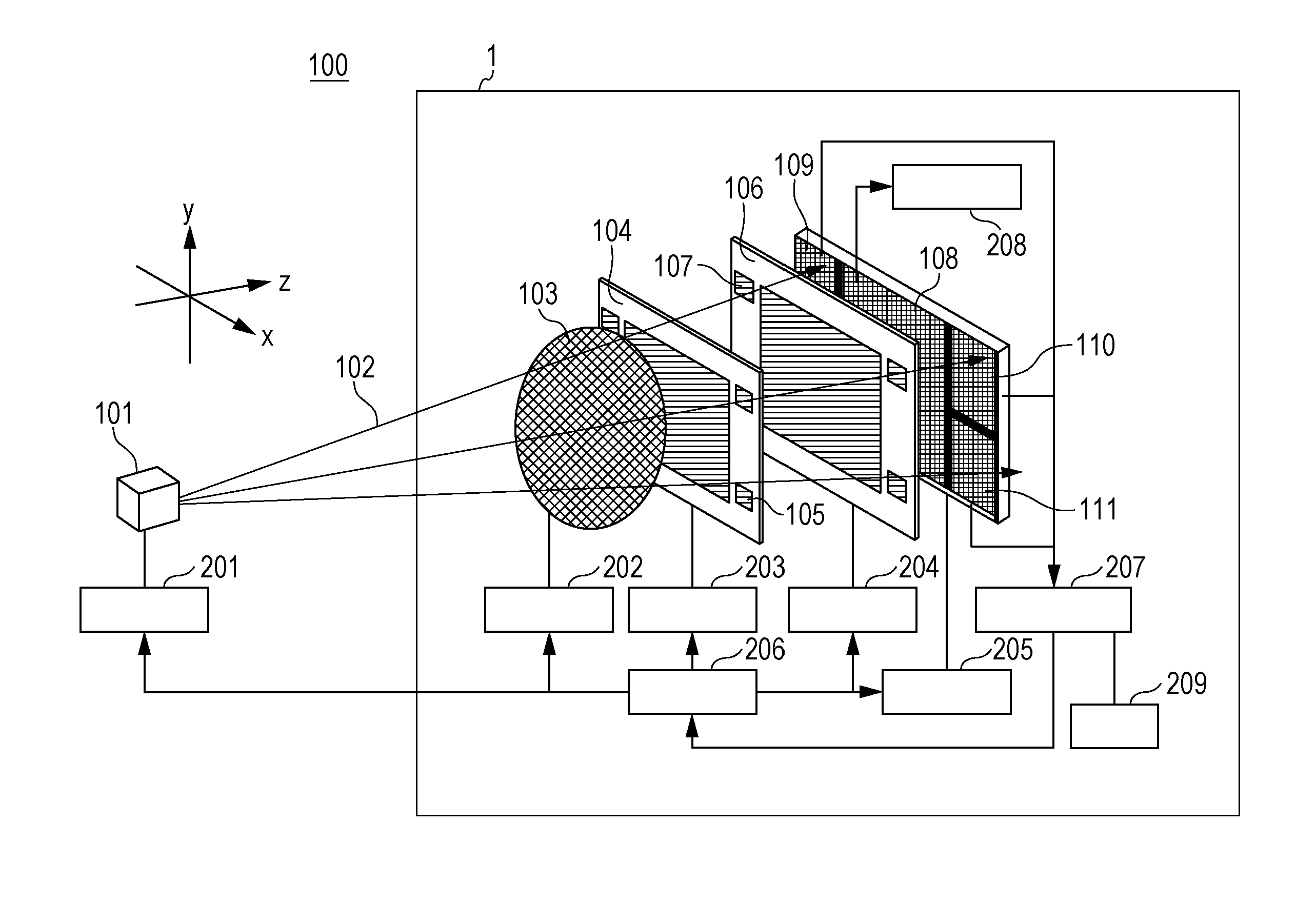
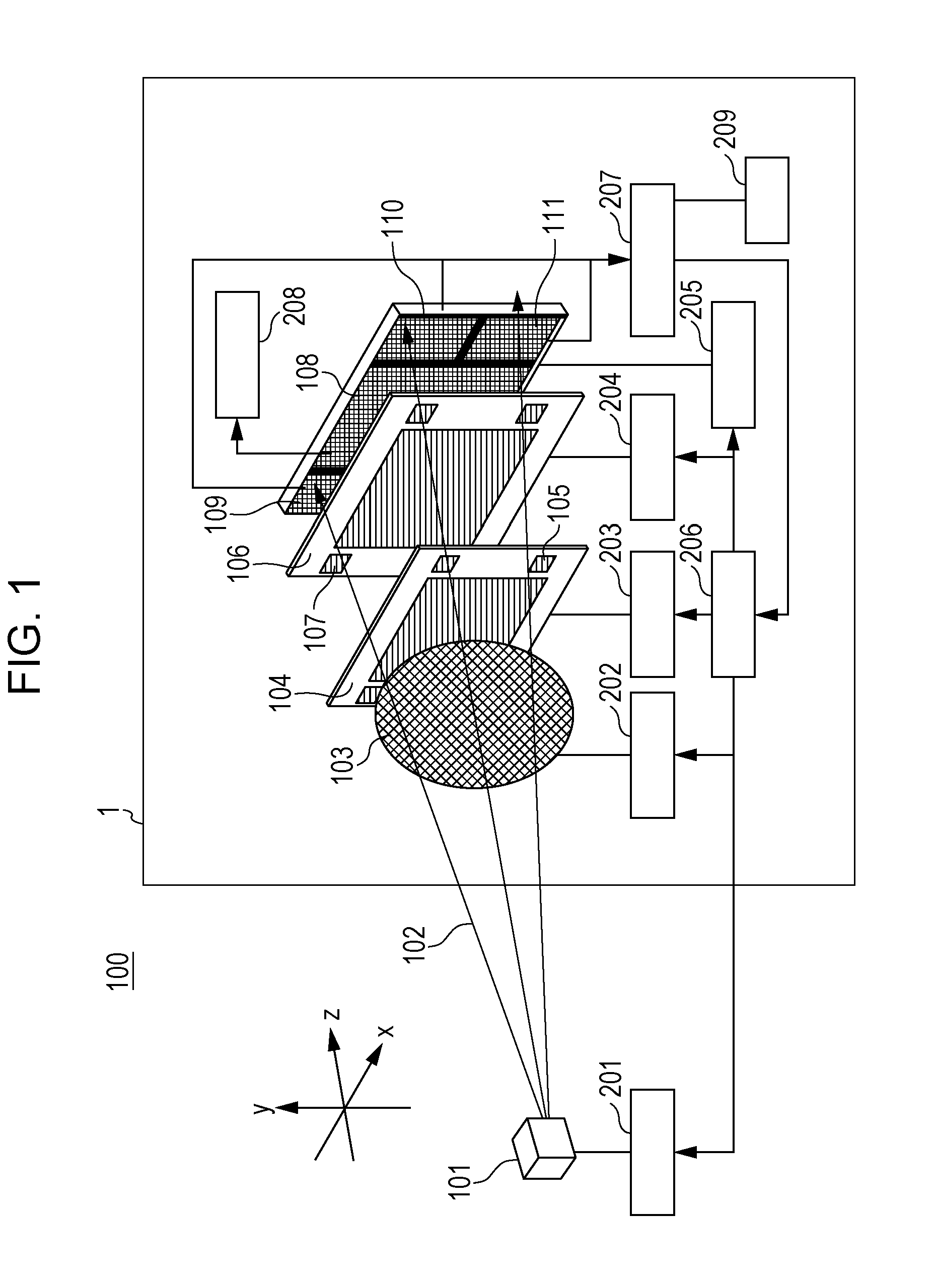
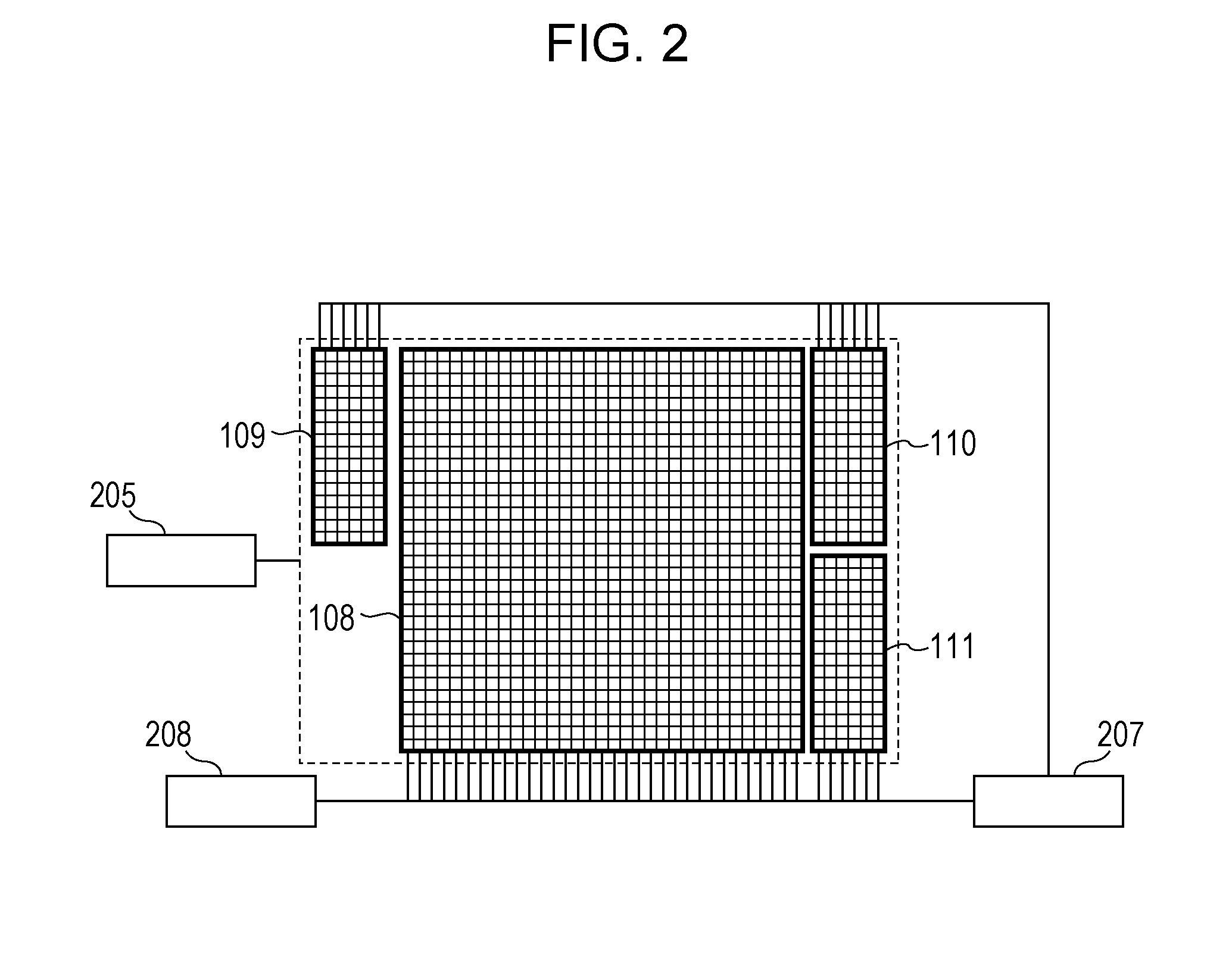
[0043]FIG. 1 is a schematic diagram illustrating the configuration of an X-ray imaging apparatus according to a first embodiment. An X-ray imaging apparatus 1 illustrated in FIG. 1 includes a diffraction grating (hereinafter referred to as a first grating) as a first optical device and an absorption grating (hereinafter referred to as a second grating) as a second optical device. A first grating 104 diffracts X-rays 102 radiated from an X-ray source 101. A second grating 106 screens part of the X-rays from the first grating 104. The X-ray imaging apparatus 1 further includes a detection unit that detects X-rays from the second grating 106, a movement unit that moves some components of the X-ray imaging apparatus 1, and calculators that calculate information regarding a subject and the amount of alignment of each component on the basis of a result of the detection performed by the detection unit. The amount of alignment of each component refers to the amount by which each component i...

second embodiment

[0093]An X-ray imaging apparatus according to this embodiment is different from the X-ray imaging apparatus 1 according to the first embodiment in that the X-ray imaging apparatus according to this embodiment includes a fifth detector 114 and gratings (hereinafter referred to as alignment patterns) having periodic structures as alignment marks. Other components are the same as those according to the first embodiment.

[0094]As illustrated in FIG. 12, the X-ray imaging apparatus according to this embodiment includes the fifth detector 114 under the second detector 109, and the second to fifth detectors 109 to 114 perform detection for realizing alignment.

[0095]In this embodiment, diffraction gratings are used as the alignment patterns of the first grating 104 and absorption gratings are used as the alignment patterns of the second grating 106. Moiré fringes are formed by overlapping the corresponding alignment patterns. The alignment is performed by detecting the moiré fringes using th...

example 1

[0121]In this example, a more specific example of the first embodiment will be described. In this example, a rotating target X-ray generation device composed of molybdenum is used as the X-ray source 101. The X-ray source 101 generates divergent X-ray beams 102, and the X-ray beams 102 enter the first grating 104, the second grating 106, and the first detector 108 or the second to fourth detectors 109 to 111 in this order. The period of the pattern of the first grating 104 is 6.1 μm, and the amount of phase modulation is a quarter of the Kα1 wavelength of molybdenum. The period of the pattern of the second grating 106 is 8.2 μm, and the X-ray screening ratio is 80%.

[0122]Three or more gold spheres are fixed to regions outside a grating region of each of the first grating 104 and the second grating 106 in the same plane as each of the first grating 104 and the second grating 106 as the alignment marks. The diameters of the gold spheres may be larger than the pixel sizes of the second...


PUM


Abstract

An X-ray imaging apparatus includes an optical device configured to form a periodic pattern using X-rays radiated from an X-ray source, an alignment mark of the optical device, a first detector, a second detector, and a movement unit configured to change at least either a position of the optical device or an angle of the optical device on the basis of a result of detection performed by the second detector. The first detector detects X-rays that have passed through the optical device and a subject, and the second detector detects X-rays that have passed through the alignment mark. The movement unit includes a movement instruction section that instructs the optical device to move on the basis of the result of the detection performed by the second detector and movement sections that move the optical device on the basis of the instruction issued by the movement instruction section.

Description

BACKGROUND OF THE INVENTION[0001]1. Field of the Invention[0002]The present invention relates to an X-ray imaging apparatus and an X-ray imaging system.[0003]2. Description of the Related Art[0004]In these years, imaging methods called “X-ray phase contrast imaging” are being developed in which contrast is generated on the basis of changes in the phases of X-rays that have passed through a subject. As one of such X-ray phase contrast imaging methods, an imaging method called “X-ray Talbot interferometry” that uses Talbot interference has been proposed in International Publication No. WO 04 / 058070.[0005]An outline of the X-ray Talbot interferometry will be described. In imaging realized by the X-ray Talbot interferometry, an X-ray imaging apparatus including an X-ray source whose spatial coherence is high, an diffraction grating that diffracts X-rays and that forms an interference pattern (self-image) having a light / dark period at a certain position, and a detector that detects the X...

Claims


Application Information

Patent Timeline
IPC IPC(8): G01N23/20
CPCG01N23/20075A61B6/4035A61B6/4266A61B6/4291A61B6/484
Inventor YAMAGUCHI, KIMIAKI
Owner CANON KK
Why Eureka
Try Eureka