Thermal Therapy Device

a technology of thermal therapy and devices, applied in the field of thermal therapy devices, can solve the problems of less desirable devices for users, clumping, and devices that fail to maintain pliable and flexible characteristics, and achieve the effects of preventing clumping, preventing clumping, and preventing adjacent formations from bonding/clumping together during the liquid-to-solid phase transition

Active Publication Date: 2014-05-08
PROFESSIONAL PRODS
View PDF18 Cites 1 Cited by
  • Summary
  • Abstract
  • Description
  • Claims
  • Application Information

AI Technical Summary

Benefits of technology

[0017]In accordance with a first preferred mode, the means for preventing clumping of adjacent discrete ice / absorber formations is provided by the addition of a plurality of physical barrier particulate added into the mixture of the hydrophillic absorbers and liquid solution. The physical barriers are preferably particulate of polypropylene, however can be any suitable saturated hydrocarbon or synthetic polymer suitable for the intended purpose. The particulate are preferably substantially planar, and may have flat, curved, curvilinear, or other non-flat profiles. The polypropylene or other barrier components are preferably mixed in a ratio of about 1-85% of the total anticipated volume of the mixture. The planar components can be sheets of polypropylene added to the mixture of hydrophillic absorbers and liquid solution which experimentation has shown to tend to position themselves between adjacent discrete ice / absorber formations during liquid-to-solid phase transition and therefor act as a means for physically separating at least two adjacent absorbers therefor providing a means for preventing clumping. As a result, the occurrence of adjacent formations bonding / clumping together during the liquid-to-solid phase transition is substantially reduced. Experimentation has shown that the operable life of the thermal therapy device is extended to at least 4 times longer than that of prior art devices. As such the device of the present invention is highly more marketable to user who often employ thermal therapy devices, such as athletes, medical professionals, and others.
[0018]In addition to reducing clumping, the plurality of planar components act to increase the thermal resistance through the thermal therapy device. Further, in other modes of the invention, the device may additionally include a plurality of hydrophobic beads which also increase the thermal resistance through the device. The beads may be in the form of spherical beads and / or other elongated shapes.

Problems solved by technology

This can include wrapping bags of ice around the injury, however is not preferred due to the lack of temperature control and possible damage(frost-bite) to the skin and surrounding tissue.
The device to Kolen is considered a great advance in the art, however, experimentation has shown that the device fails to maintain its pliable and flexible characteristics after extended cycles of freezing / thawing past the conventional operating period.
This makes the device less desirable to users after prolonged operative employment.
Despite the assertions in the disclosure to Kolen that the discrete absorbers retain their discrete forms over time, clumping has been shown to occur during the freezing cycle after prolonged and repeated use of the device; as the water migrates out and solidifies around the discrete absorbers, adjacent discrete ice / absorber formations will tend to bond together, creating clumps.
In addition, the absorbers will gradually break down into ever small pieces with each usage, this also increases the tendency to clump.
Those skilled in the art could easily ascertain that repeated cycles of freezing / melting will cause the absorber material to degrade and wear.
Still further, an additional downfall noted about the device is the manner in which the device is frozen and / or stored by the user.
The air membrane allows excess air escape the container in order to prevent a rupture of the container, however, there is still a substantial increase in the overall volume of the device.
Various limitations of the related art will become apparent to those skilled in the art upon a reading and understanding of the specification below and the accompanying drawings.

Method used


Image

  • Thermal Therapy Device
  • Thermal Therapy Device
  • Thermal Therapy Device

Examples


Embodiment Construction

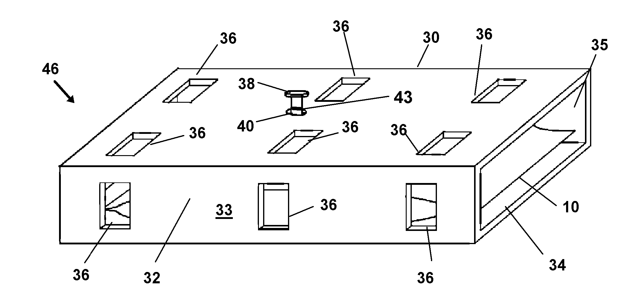
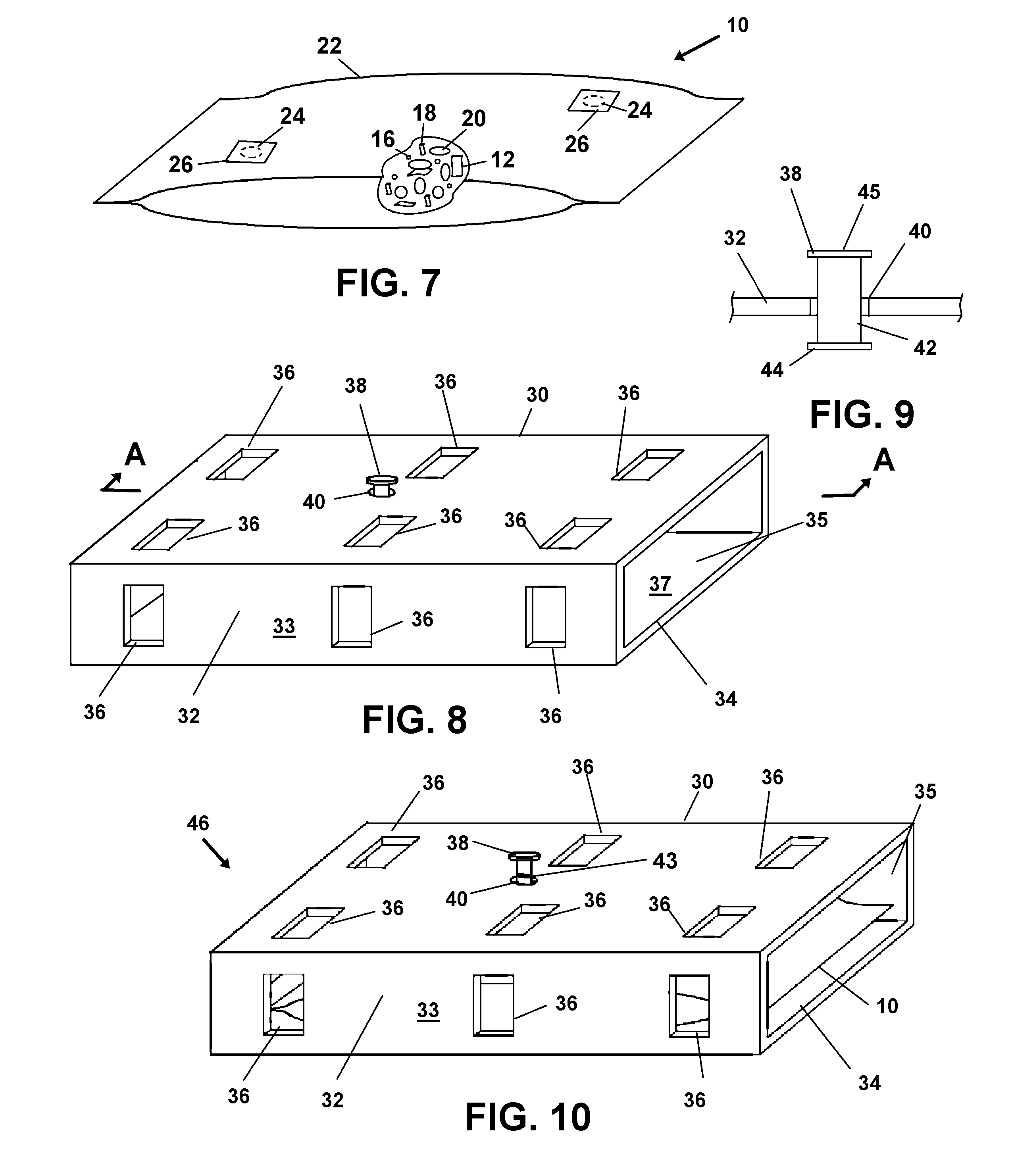
[0038]In this description, the directional prepositions of up, upwardly, down, downwardly, front, back, top, upper, bottom, lower, left, right and other such terms refer to the device as it is oriented and appears in the drawings and are used for convenience only; they are not intended to be limiting or to imply that the device has to be used or positioned in any particular orientation.

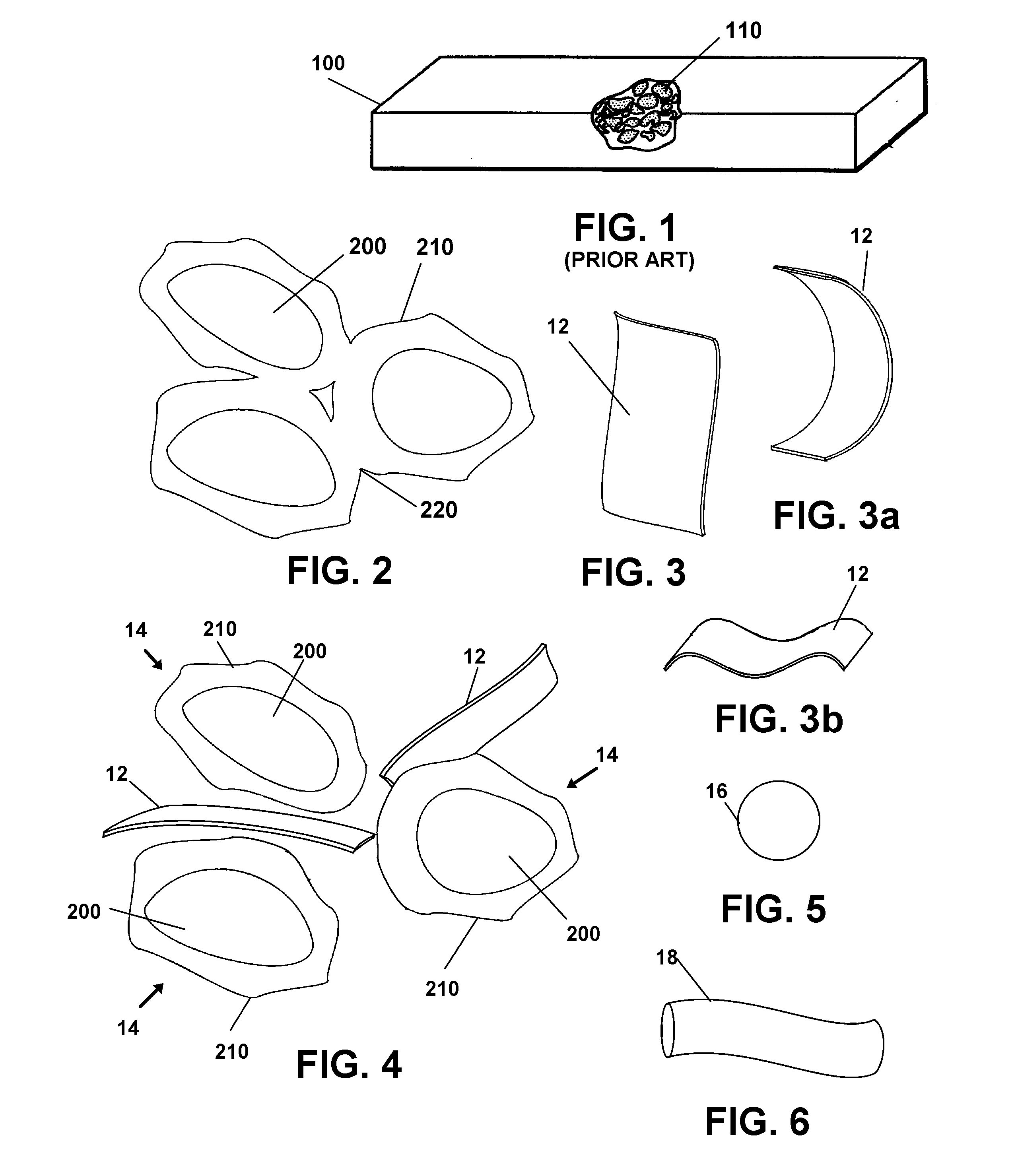
[0039]Now referring to drawings in FIGS. 1-10, wherein similar components are identified by like reference numerals, there is seen in FIG. 1 a view of the prior art thermal therapy device 100. The prior art device 100 generally comprises a flexible container housing a plurality pre-hydrated hydrophillic absorbers 110. The device 100 is considered a great advance in the art as it provides a substantially pliable thermal therapy device 100 through a limited operative period of freezing / thawing cycles. However, experimentation has shown that the device 100 loses substantial pliability after prolonged and...


PUM

PropertyMeasurementUnit
sizeaaaaaaaaaa
surface areaaaaaaaaaaa
volume ratioaaaaaaaaaa

Abstract

A thermal therapy device comprising a flexible, water-impermeable container containing a plurality of discrete, non-water-soluble hydrophillic absorbers, a hydrating liquid mixture comprising water, means for physically separating at least two adjacent absorbers thereby providing a means for preventing clumping, and a plurality of insulating members. The means for preventing clumping maintaining the pliability of the device in a frozen state after prolonged and extend cycles of freezing/thawing. A rigid storage container is also provided.

Description

BACKGROUND OF THE INVENTION[0001]1. Field of the Invention[0002]The present invention relates to thermal therapy devices. More particularly the invention relates to thermal therapy devices comprising a plurality of hydrated hydrophillic absorbers and a means for preventing clumping of the absorbers over extended cycles of freezing / melting.[0003]2. Prior Art[0004]Thermal therapy is a conventional method of rehabilitating injuries such as bruises and sprains to bone, muscle, ligaments, tendons, and skin. Heat therapy is often employed to loosen joint tissue while cold therapy is preferred for reducing swelling, pain, and to promote healing. Cold therapy is also known to be beneficial after surgery additionally for reducing swelling and promoting healing. By lowering the temperature of the injured tissue, the metabolic rate is reduced which allows the tissue to survive and recover during the period following the injury.[0005]A conventional cold therapy method is simply to apply ice to ...

Claims


Application Information

Patent Timeline
Patent Type & Authority Applications(United States)
IPC IPC(8): A61F7/10
CPCA61F7/10A61F7/02A61F2007/0203A61F2007/0209A61F2007/0211A61F2007/0214A61F2007/0215
Inventor NEBOLON, JOSEPH FRANCISGARDNER, SARAH JOAN
Owner PROFESSIONAL PRODS
Why Eureka
Try Eureka