Vibration control structure for steering wheel

a technology of vibration control and steering wheel, which is applied in the direction of vehicular safety arrangements, vehicle components, pedestrian/occupant safety arrangements, etc., can solve the problems of excessive rearward movement of the bag holder, difficult to incorporate the above-described dynamic damper in the recent steering wheel, and impaired comfort driving. , to achieve the effect of simple operation and high strength

Active Publication Date: 2014-05-15
TOYODA GOSEI CO LTD
View PDF0 Cites 27 Cited by
  • Summary
  • Abstract
  • Description
  • Claims
  • Application Information

AI Technical Summary

Benefits of technology

[0025]During the production of the above steering wheel, the horn switch mechanism is assembled to the airbag device via the elastic member. At this time, the elastic member is sandwiched by the bag holder and the slider from the front and rear thereof. Further, the elastic member is sandwiched by the bag holder and the slider from the outside and inside of the radial direction. In this way, the periphery of the annular elastic member is surrounded by the bag holder and the slider, so that the movement of the elastic member in a longitudinal direction (front-rear direction) and radial direction is restricted. As a result, the mounting strength of the elastic member is increased, as compared to a case where the elastic member is mounted only at an outer peripheral portion thereof. Further, when mounting the elastic member, it is sufficient only to sandwich the elastic member by the bag holder and the slider from the longitudinal direction (front-rear direction) and radial direction, as described above.<2> In the vibration control structure for the steering wheel of <1>, the bag holder includes a mounting portion disposed around the mounting hole and intersecting the bag holder along the front-rear direction,
[0042]According to the vibration control structure for the steering wheel, it is possible to mount an elastic member with high strength by performing a simple operation.

Problems solved by technology

When vibration in a vertical direction or lateral direction is transmitted to a steering wheel during high-speed travelling of a vehicle or idling of an in-vehicle engine, the vibration is transmitted to a driver through his hands grasping the steering wheel and therefore a comfortable driving may be impaired.
Here, since the airbag device occupies a substantial portion of an internal space of the steering wheel, it is difficult to incorporate the above-described dynamic damper in a recent steering wheel.
In this way, excessive rearward movement of the bag holder, in turn, the airbag device is restricted.

Method used


Image

  • Vibration control structure for steering wheel
  • Vibration control structure for steering wheel
  • Vibration control structure for steering wheel

Examples


first embodiment

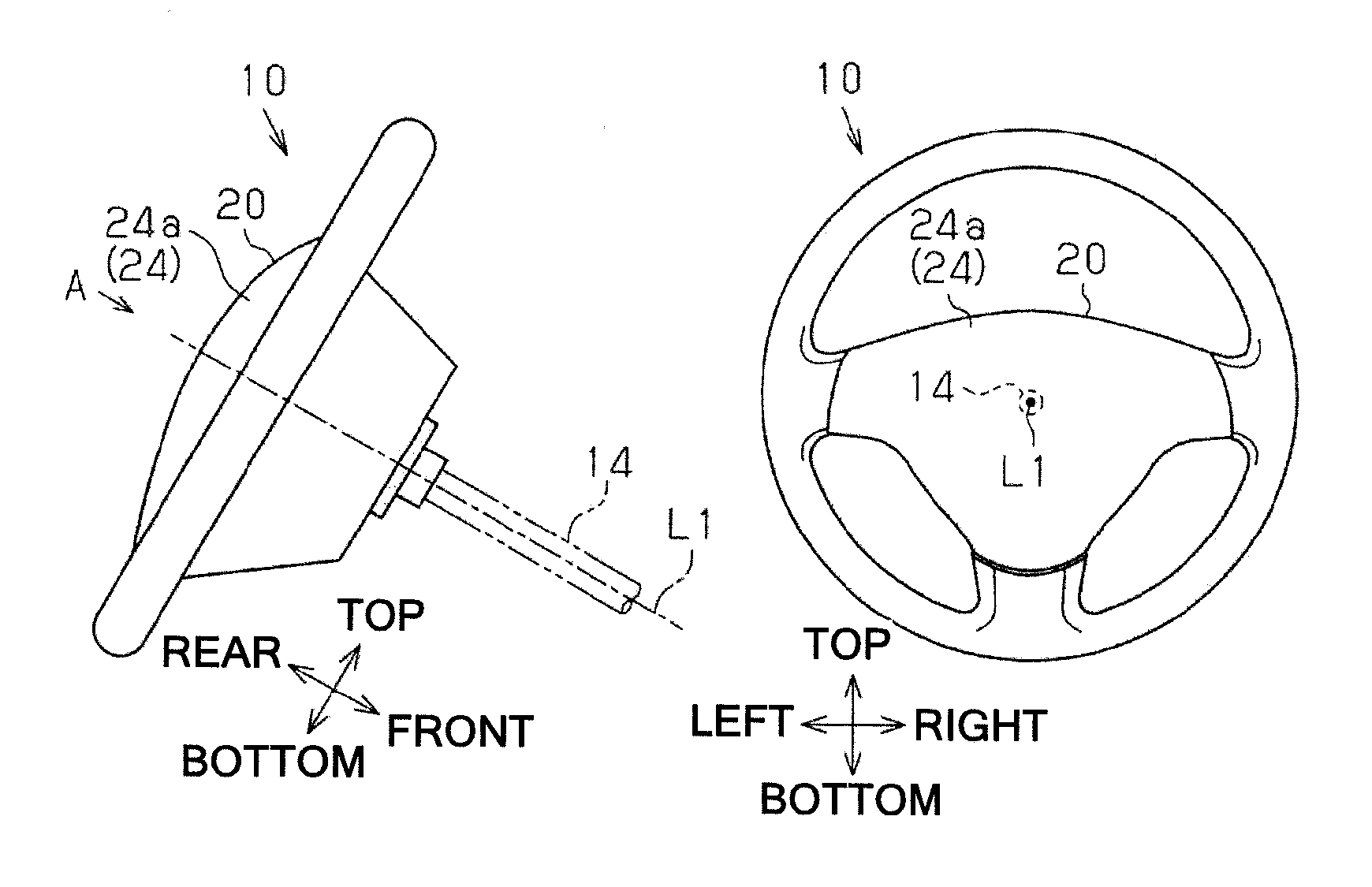
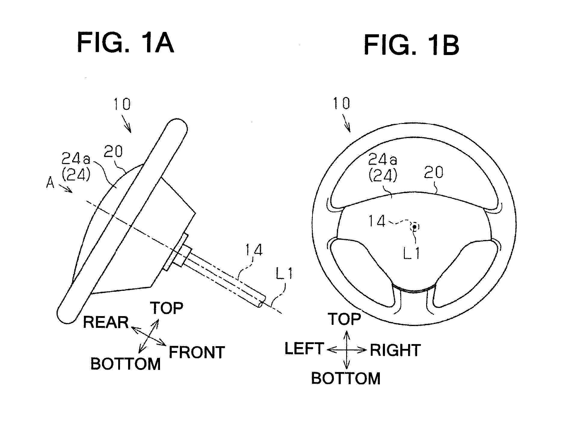
[0061]Hereinafter, a first embodiment of a vibration control structure for a steering wheel will be described with reference to FIG. 1 to FIG. 11.

[0062]As shown in FIG. 1A, a steering shaft 14 is disposed on a front side (right side in FIG. 1A) of a driver's seat of a vehicle in an inclined state where the steering shaft 14 becomes higher toward the driver's seat side (left side in FIG. 1A). The steering shaft 14 extends in a longitudinal direction (front-rear direction) along an axis L1 and rotates about the axis L1. A steering wheel 10 is mounted to a rear end portion of the steering shaft 14 so as to rotate integrally therewith.

[0063]In the first embodiment, each part of the steering wheel 10 will be described with respect to the axis L1 of the steering shaft 14. A direction along the axis L1 is referred to as “a longitudinal direction (front-rear direction)” of the steering wheel 10. And, among the directions along a plane perpendicular to the axis L1, a standing direction of th...

second embodiment

[0152]Next, a second embodiment of a vibration control structure for a steering wheel will be described with reference to FIG. 12 to FIG. 14.

[0153]The second embodiment uses the elastic member 41 which has a form different from the first embodiment.

[0154]FIG. 13A shows a sectional structure of the horn switch mechanism 30 mounted to the bag holder 21 and FIG. 14 shows a sectional structure of the horn switch mechanism 30 in a cross-section different from FIG. 13. More specifically, FIG. 13A shows a sectional structure taken along a line 13-13 in FIG. 12 and FIG. 14 shows a sectional structure taken along a line 14-14 perpendicular to the line 13-13 in FIG. 12.

As shown in FIG. 13A and FIG. 14, a recess 32d is formed over the entire periphery of the outer peripheral portion of the cylindrical portion 32a of the pin holder 32 in between the enlarged diameter portion 32b and the stepped portion 32c. The portion of the cylindrical portion 32a that is sandwiched by the stepped portion 32c...

third embodiment

[0170]Next, a third embodiment of a vibration control structure for a steering wheel will be described with reference to FIG. 15.

[0171]The third embodiment is the same as the second embodiment in the respects that the elastic member 41 is configured by the inner cylinder portion 41c, the outer cylinder portion 41d and the connecting portion 41e. The third embodiment is different from the second embodiment in the respects that the connecting portion 41e is not disposed at end portions in a longitudinal direction (front-rear direction) of the inner cylinder portion 41c and the outer cylinder portion 41d but disposed at intermediate portions thereof. The intermediate portion in a longitudinal direction (front-rear direction) of the inner cylinder portion 41c and the intermediate portion in a longitudinal direction (front-rear direction) of the outer cylinder portion 41d are connected by the connecting portion 41e. The connecting portion 41e is perpendicular to the longitudinal directio...


PUM


Abstract

A vibration control structure includes a fixed member, an airbag device that is provided at a front portion thereof with a bag holder having a mounting hole and is disposed at a rear side of the fixed member, a horn switch mechanism that includes a support member supported by the fixed member in a state where the horn switch mechanism is inserted through the mounting hole and a slider disposed between the support member and the mounting hole so as to be slidable in the front-rear direction, and an annular elastic member that is disposed on the rear side of the bag holder while being mounted to the outside of the slider. The airbag device serves as a damper mass of a dynamic damper and the elastic member serves as a spring of the damper mass.

Description

CROSS-REFERENCE TO RELATED APPLICATION[0001]This application claims the benefit of Japanese Patent Application Nos. 2012-248359 (filed on Nov. 12, 2012) and 2013-153841 (filed on Jul. 24, 2013), the entire contents of which are hereby incorporated by reference.BACKGROUND[0002]1. Technical Field[0003]The present invention relates to a vibration control structure for suppressing (controlling) vibration of a steering wheel in which an airbag device is incorporated.[0004]2. Related Art[0005]When vibration in a vertical direction or lateral direction is transmitted to a steering wheel during high-speed travelling of a vehicle or idling of an in-vehicle engine, the vibration is transmitted to a driver through his hands grasping the steering wheel and therefore a comfortable driving may be impaired. For this reason, techniques for suppressing (controlling) vibration of the steering wheel have been developed and proposed in the prior art. Among these techniques, there is a technique that us...

Claims


Application Information

Patent Timeline
Patent Type & Authority Applications(United States)
IPC IPC(8): B60R21/203
CPCB60R21/203B60R21/2037
Inventor ISHII, TSUTOMUHIROSE, OSAMUUMEMURA, NORIOHAYASHI, MIKINE
Owner TOYODA GOSEI CO LTD
Why Eureka
Try Eureka