System and method for manufacturing electrically isolated connection for electromagnetic gap sub assembly

a technology of electrical isolation and electromagnetic gap, which is applied in the direction of manufacturing tools, mechanical equipment, metal working equipment, etc., can solve the problem of difficult simultaneous acquisition of the gap sub

Active Publication Date: 2014-05-15
MS DIRECTIONAL LLC
View PDF12 Cites 22 Cited by
  • Summary
  • Abstract
  • Description
  • Claims
  • Application Information

AI Technical Summary

Benefits of technology

[0008]In yet another embodiment, multiple rings could be utilized with each ring mating to the anti-torsion features of an adjacent ring. In yet another embodiment, the locking ring may be affixed to the first

Problems solved by technology

This has been difficult to obta

Method used


Image

  • System and method for manufacturing electrically isolated connection for electromagnetic gap sub assembly
  • System and method for manufacturing electrically isolated connection for electromagnetic gap sub assembly
  • System and method for manufacturing electrically isolated connection for electromagnetic gap sub assembly

Examples


Embodiment Construction

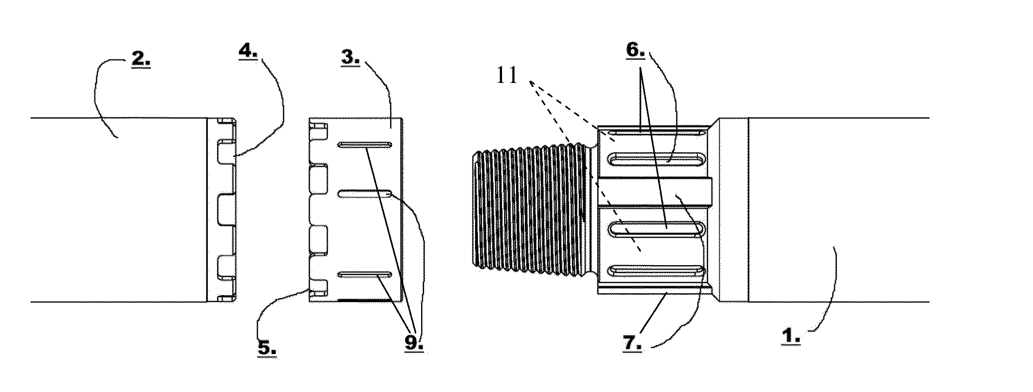
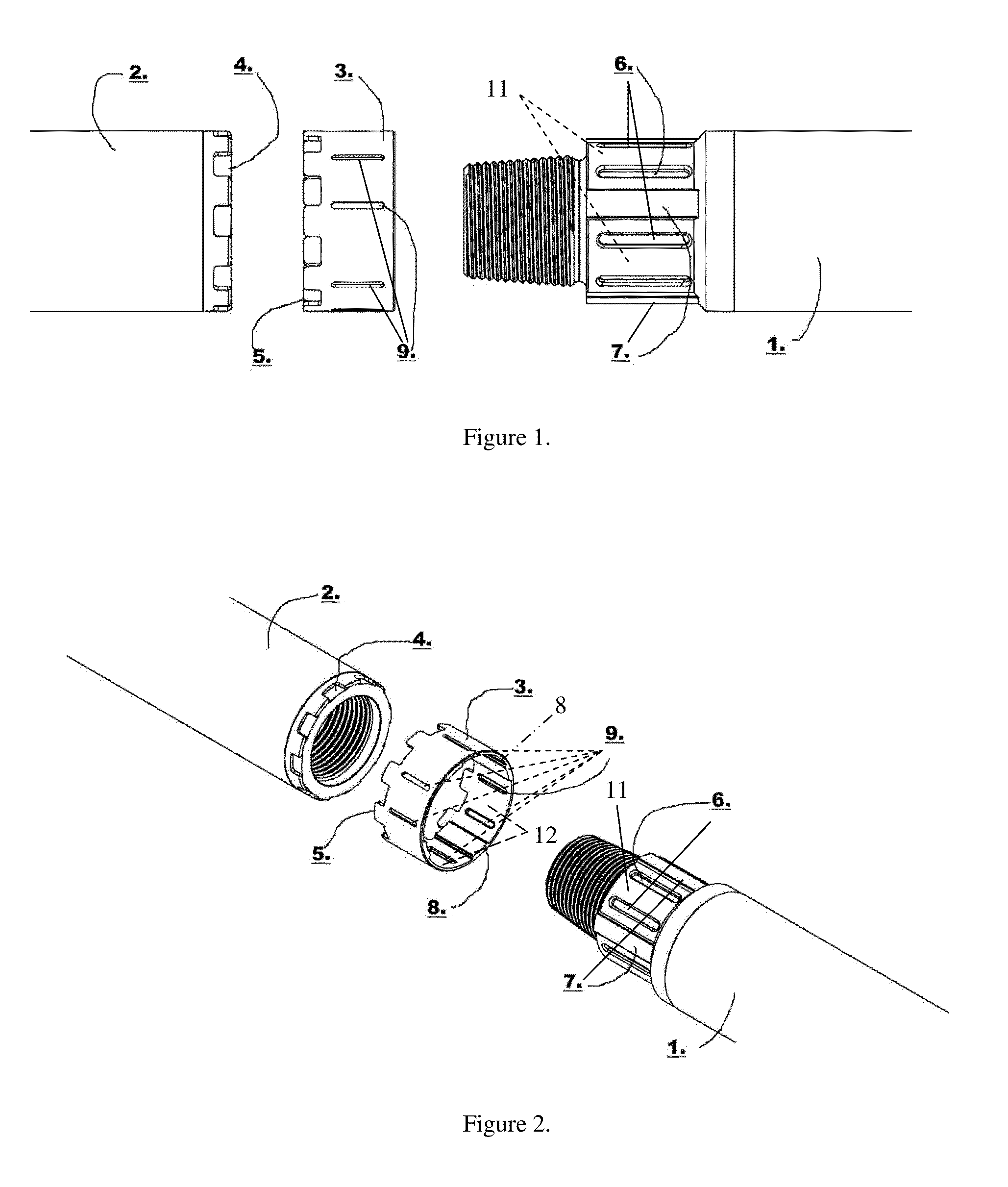
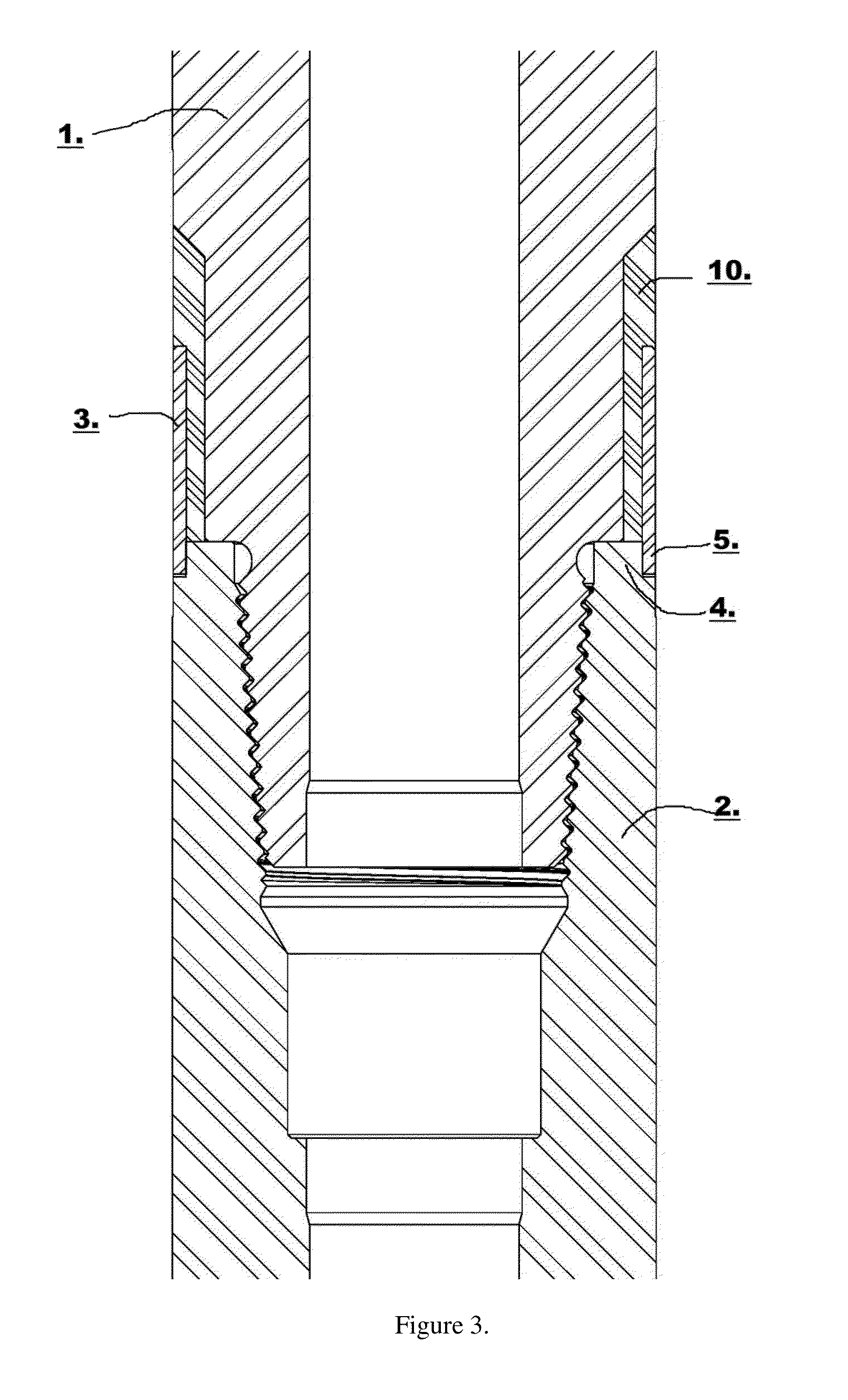
[0015]Refer now to the drawings wherein depicted elements are not necessarily shown to scale and wherein like or similar elements are designated by the same reference numeral through the several views.

[0016]Referring to the drawings in general, it will be understood that the illustrations are for the purpose of describing particular implementations of the disclosure and are not intended to be limiting thereto. While most of the terms used herein will be recognizable to those of ordinary skill in the art, it should be understood that when not explicitly defined, terms should be interpreted as adopting a meaning presently accepted by those of ordinary skill in the art.

[0017]It is to be understood that both the foregoing general description and the following detailed description are exemplary and explanatory only, and are not restrictive of the invention, as claimed. In this application, the use of the singular includes the plural, the word “a” or “an” means “at least one”, and the use...


PUM

PropertyMeasurementUnit
Angleaaaaaaaaaa
Electrical conductoraaaaaaaaaa
Torqueaaaaaaaaaa

Abstract

A gap sub assembly and methods for using the gap sub provide an electrical isolating joint that is mechanically strong enough to withstand the rigors of drilling environments, resistant to environmental effects (heat, corrosive liquids and gases, and high pressures), and maintainable. The gap sub assembly provides a male member and a female member that may be connected together, wherein a non-conductive material is applied between the two at the attachment points. A locking ring or collar affixes to both male and female members to prevent back off while drilling and preserving the electrical isolation of the gap joint. Non-conductive material may be injected between the locking ring and one or more of the male or female members.

Description

RELATED APPLICATIONS[0001]This application claims the benefit of U.S. Provisional Patent Application No. 61 / 725,224 to Holmen et al. filed on Nov. 12, 2012, which is incorporated herein by reference.FIELD OF THE INVENTION[0002]This invention relates to electrically isolating a connection in a drilling assembly and more specifically to an improved insulated gap sub-assembly.BACKGROUND OF INVENTION[0003]Modern drilling techniques employ sensors downhole and broadcast this sensor information to surface using Measurement While Drilling (MWD) telemetry. One variety of MWD telemetry, Electromagnetic (EM) telemetry, sends data to the surface using low frequency radio waves generated by producing a voltage across an insulated gap sub in a drill string or assembly. In EM telemetry applications, a carrier signal is produced by applying an alternating voltage across the insulating gap or electrical isolation in the drill string. This mechanism responsible for providing the insulated gap or ele...

Claims


Application Information

Patent Timeline
IPC IPC(8): F16L25/02
CPCF16L25/021Y10T29/49826
Inventor HOLMEN, GARRYPAYNE, JEFF
Owner MS DIRECTIONAL LLC
Why Eureka
Try Eureka