Input system

a technology of input system and capacitance variation, applied in the field of input system, can solve the problems of pen not being discriminated from one another, difficulty in sensing the mutual capacitance variation cm when the touch detection circuit is touched by the stylus pen, and affecting the accuracy of the input signal, so as to achieve the effect of reducing the thickness of the elastic member

Active Publication Date: 2014-05-15
LG DISPLAY CO LTD
View PDF5 Cites 59 Cited by
  • Summary
  • Abstract
  • Description
  • Claims
  • Application Information

AI Technical Summary

Benefits of technology

[0026]An object of the present invention is to provide an input system which may implement a stylus pen without a battery, detect both touch by fingers and touch by the stylus pen, and increase sensitivity to writing pressure.
[0029]When the stylus pen presses the surface of the sensor panel, the thickness of the elastic member may be reduced and thus an interval between the primary coil and the secondary coil may be reduced as pressure generated by pressing the stylus pen onto the surface of the sensor panel is increases.

Problems solved by technology

However, when the touch detection circuit is touched by a stylus pen rather than fingers, a contact area of the tip of the stylus pen with the surface of a sensor panel is relatively small, mutual capacitance variation ΔCm between the electrodes is small, and thus sensing of the mutual capacitance variation ΔCm when the touch detection circuit is touched by the stylus pen may be difficult.
Further, if the tip of the stylus pen is smaller than the electrodes provided on the sensor panel for sensing, distortion of coordinates may occur according to presence or absence of the electrodes, and this may directly influence sensitivity.
Further, in case of finger touch and stylus pen touch, when the same touch detection circuit is used, touch by a palm contacting the electrodes and touch by the stylus pen during input by the stylus pen may not be discriminated from one another.
That is, it may be difficult for the detection circuit of FIG. 1 to perform a palm rejection function when the detection circuit is touched by the stylus pen.
First, since a contact area of the tip of the stylus pen with the sensor panel surface is relatively small, mutual capacitance variation ΔCm between the electrodes is small, and thus sensing of the mutual capacitance variation ΔCm when the touch detection circuit is touched by the stylus pen may be difficult.
Second, if the tip of the stylus pen is smaller than the electrodes provided on the sensor panel for sensing, distortion of coordinates may occur according to presence or absence of the electrodes, and this may directly influence sensitivity.
Third, in case of finger touch and stylus pen touch, when the same touch detection circuit is used, touch by a palm contacting the electrodes and touch by the stylus pen during input by the stylus pen may not be discriminated from one another.
That is, it may be difficult for the capacitive-type touchscreen to perform a palm rejection function when the touchscreen is touched by the stylus pen.

Method used


Image

  • Input system
  • Input system
  • Input system

Examples


Embodiment Construction

[0063]Reference will now be made in detail to the preferred embodiments of the present invention, examples of which are illustrated in the accompanying drawings. Wherever possible, the same reference numbers will be used throughout the drawings to refer to the same or like parts.

[0064]Hereinafter, an input system and a touch detection method using the same in accordance with one embodiment of the present invention will be described with reference to the accompanying drawings.

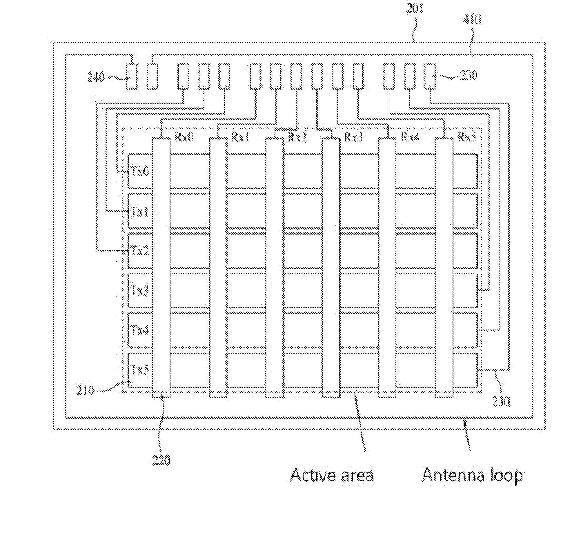
[0065]The input system in accordance with the embodiment of the present invention basically has a structure of detecting finger touch in a capacitive type, and may detect stylus pen touch by resonance through an inner resonant circuit of a stylus pen and an antenna loop at the edge area of a sensor panel. That is, the input system may detect stylus pen touch, which is limited in detection in the capacitive type, without influence on a contact area or the shape of an electrode pattern by changing the configuratio...


PUM


Abstract

Discussed is an input system that includes a sensor panel including plural first and second channels intersecting each other, a stylus pen including a first core and a second core divided from each other, a primary coil and a secondary coil wound on the first and second cores, an elastic member interposed between the first core and the second core, a resonant capacitor and a switch connected to the secondary coil in series, and a conductive tip connected to the primary coil, a ground unit connected to the stylus pen, an antenna loop formed at the edge area of the sensor panel, and a touch controller connected to the first and second channels and the antenna loop.

Description

[0001]This application claims the benefit of Korean Patent Application No. 10-2012˜0127906, filed on Nov. 13, 2012, which is hereby incorporated by reference as if fully set forth herein.BACKGROUND OF THE INVENTION[0002]1. Field of the Invention[0003]The present invention relates to an input system, and more particularly, to an input system which may implement a stylus pen without a battery, detect both touch by fingers and touch by the stylus pen, and increase sensitivity to writing pressure.[0004]2. Discussion of the Related Art[0005]As the information age has arrived, the field of displays visually expressing electrical information signals has rapidly developed, and in order to satisfy such a trend, various flat display devices having excellent performance, such as thin thickness, light weight and low power consumption, have been researched and rapidly replaced conventional cathode ray tubes (CRTs).[0006]Flat display devices include liquid crystal displays (LCDs), plasma display ...

Claims


Application Information

Patent Timeline
Patent Type & Authority Applications(United States)
IPC IPC(8): G06F3/041
CPCG06F3/041G06F3/03545G06F3/046G06F2203/04106G06F3/0442G06F3/0412G06F3/0416G06F3/044
Inventor JEONG, IL-DOO
Owner LG DISPLAY CO LTD
Why Eureka
Try Eureka