Light guide plate and area light source device

Active Publication Date: 2014-05-15
TOHOKU DENSHI CO LTD
View PDF7 Cites 66 Cited by
  • Summary
  • Abstract
  • Description
  • Claims
  • Application Information

AI Technical Summary

Benefits of technology

[0025]In accordance with one or more embodiments of the present invention, an area light source device includes: a light guide plate; and a light source that emits the light to the end surface of the light introduction part in the light guide plate. In the area light source device according to one or more embodiments of the present invention, the light leaking from the lighting-region-side end surface of the directivity change pattern formed in the light guide plate is decreased, so that the effective lighting region can be prevent

Problems solved by technology

However, even if the flat light guide plate can be thinned, there is a limitation to a reduction of a height of a light source including an LED.
When the light source is projected from the light guide plate, whole light emitted from the light source is not incident to the

Method used


Image

  • Light guide plate and area light source device
  • Light guide plate and area light source device
  • Light guide plate and area light source device

Examples


first embodiment

Configuration of First Embodiment

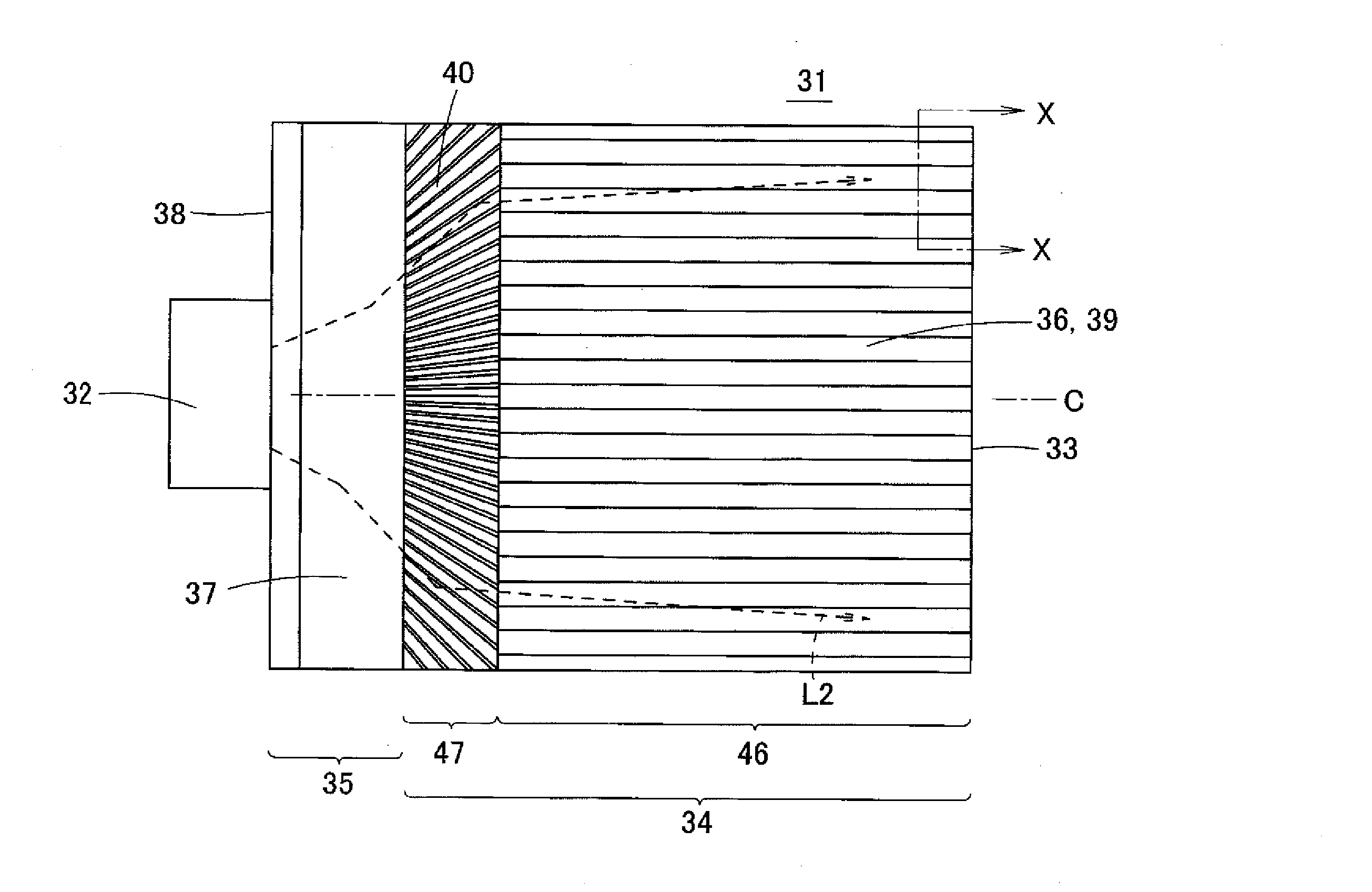
[0056]A configuration of a first embodiment of the present invention will be described below with reference to FIGS. 6A, 6B, 7, and 8. FIG. 6A is a plan view illustrating an area light source device 31 of the first embodiment. FIG. 6B is an enlarged sectional view taken on a line X-X in FIG. 6A, and illustrates a lenticular lens 36 provided on a surface of a light guide plate 33. FIG. 7 is a schematic sectional view along a vertical direction (a direction perpendicular to a light incident surface 38) of the area light source device 31, and illustrates a behavior of light beam in the light guide plate 33. FIG. 8 is a sectional view illustrating a shape of a directivity change pattern in a section parallel to a light incident surface and a partially enlarged section of the directivity change pattern. Because the area light source device 31 of the first embodiment is also illustrated by the perspective view in FIG. 3, the area light source device 31 of ...

second embodiment

[0098]FIG. 17 is a perspective view illustrating an area light source device 71 according to a second embodiment of the present invention. FIG. 18A is a plan view of the area light source device 71. FIG. 18B is a sectional view taken on a line Y-Y in FIG. 18A.

[0099]In the area light source device 71 of the second embodiment, a light diffusion pattern 72 is formed on the upper surface and / or lower surface of the light introduction part 35 in order to horizontally spread the directivity of the reflected light. As illustrated in FIG. 18B, the light diffusion pattern 72 may be formed by arraying vertically-extending V-grooves 72a in parallel with one another, or the light diffusion pattern 72 may be a pattern having a lenticular-lens shape or a random shape. In the structure of the second embodiment, the light is sent to the side surface direction of the light guide plate 33 while horizontally spread by the light diffusion pattern 72, thereby preventing darkening of a side edge portion ...

third embodiment

[0102]FIG. 20 is a plan view illustrating an area light source device 81 according to a third embodiment of the present invention. FIG. 21 is a partially enlarged perspective view illustrating the light introduction part 35 of the area light source device 81.

[0103]In the area light source device 81 of the third embodiment, a light diffusion pattern 82 that horizontally spreads the light is provided in a region facing at least the light source 32 in the light incident surface 38 of the light introduction part 35. As illustrated in FIG. 21, the light diffusion pattern 82 may be formed into a cylindrical lens shape in which the convex lenses extending in the height direction are horizontally arrayed. Alternatively, the light diffusion pattern 82 may be constructed by arraying the V-grooves extending in the height direction in parallel with one another, or the light diffusion pattern 82 may be a pattern having a random shape.

[0104]In the area light source device 81 having the above stru...


PUM


Abstract

A light guide plate has an end surface configured to have light incident thereon, a light introduction part that confines light incident through the end surface, and a light guide plate body disposed to be continuously joined to the light introduction part. The light guide plate body has a thickness smaller than a maximum thickness of the light introduction part. The light guide plate body outputs the incident light to an outside from a lighting region through a light exit part. The light introduction part includes an inclined surface in at least one of a light-exit-side surface and an opposite surface of the light-exit-side surface. The directivity change pattern changes directivity of the light passing to the lighting region from the light introduction part.

Description

CROSS-REFERENCE TO RELATED APPLICATION[0001]The present application claims priority from Japanese Patent Application No. 2012-251396, filed on Nov. 15, 2012, the subject matter of which is hereby incorporated by reference.BACKGROUND[0002]1. Technical Field[0003]The present invention relates to a light guide plate and an area light source device. Specifically, the present invention relates to an area light source device that is used as a backlight for a liquid crystal display device and a light guide plate constituting the area light source device.[0004]2. Related Art[0005]Nowadays, there is increasing a demand for a low profile of an area light source device with the progress of a low-profile mobile device provided with the area light source device. In order to thin the area light source device, it is necessary to thin a light guide plate. However, even if the flat light guide plate can be thinned, there is a limitation to a reduction of a height of a light source including an LED. ...

Claims


Application Information

Patent Timeline
IPC IPC(8): F21V8/00
CPCG02B6/0018G02B6/0016G02B6/002G02B6/003G02B6/0038G02B6/10G02B6/122G02F1/1335
Inventor KURATA, GOUO
Owner TOHOKU DENSHI CO LTD
Why Eureka
Try Eureka