
Light Output Device with Movable Lightguide System

a technology of light output device and light guide, which is applied in the direction of instruments, fibre light guides, lighting and heating apparatus, etc., can solve the problems of expensive and relatively complicated light output devices

Inactive Publication Date: 2014-05-15
SIGNIFY HLDG BV
View PDF8 Cites 24 Cited by
  • Summary
  • Abstract
  • Description
  • Claims
  • Application Information

AI Technical Summary

Benefits of technology

The present invention provides an improved light-output device that can produce different light-output functions with high efficiency and without the need for additional components. The device is simple to use, and to switch between functions, all that is required is to move the light-guiding system relative to the light-source arrangement. The device is also more robust and cost-efficient due to the inclusion of one or several light-mixing devices that increase tolerance in the positioning of the light-guiding system in relation to the light-source arrangement.

Problems solved by technology

However, this might result in a relatively complicated and costly light-output device.

Method used


Image

  • Light Output Device with Movable Lightguide System
  • Light Output Device with Movable Lightguide System
  • Light Output Device with Movable Lightguide System

Examples


Embodiment Construction

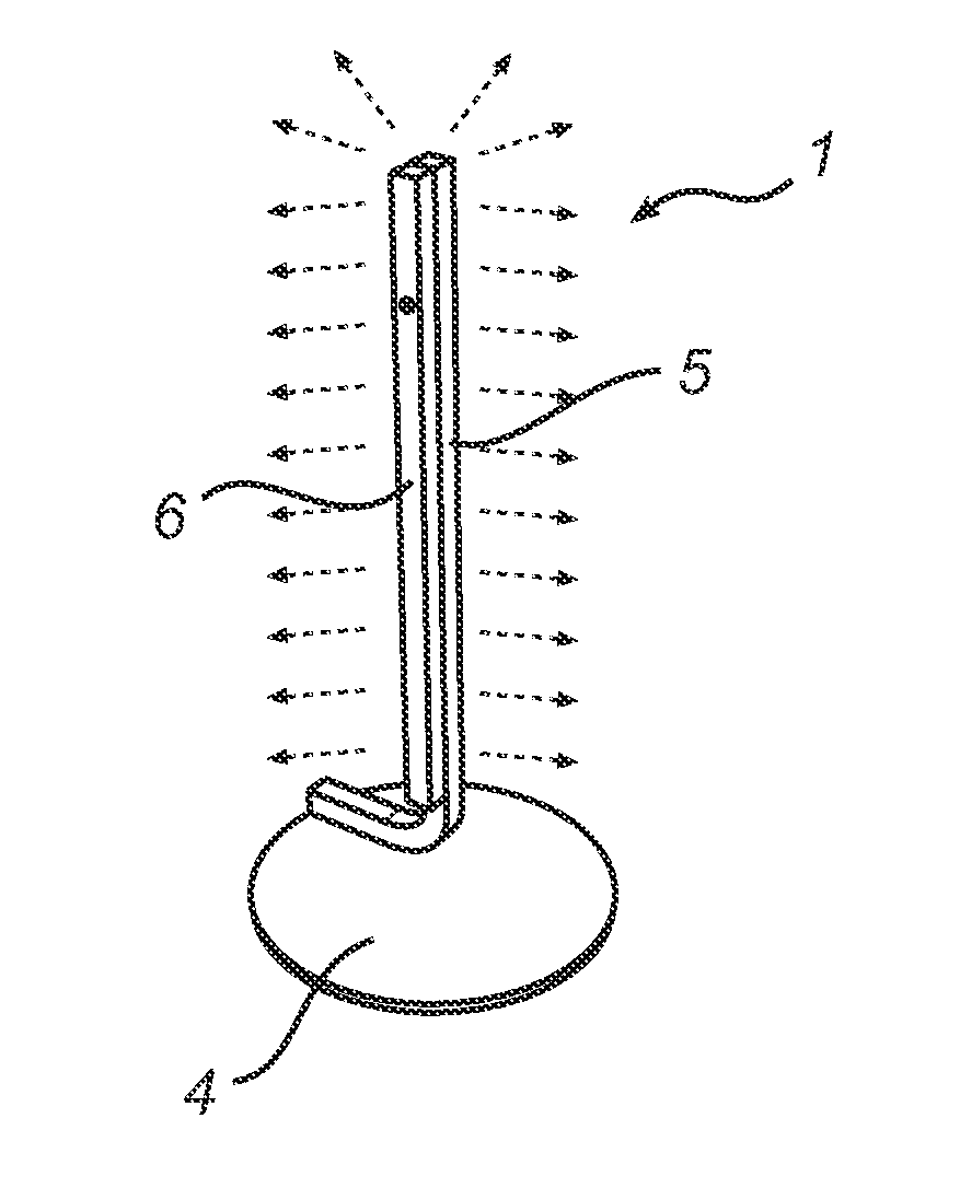
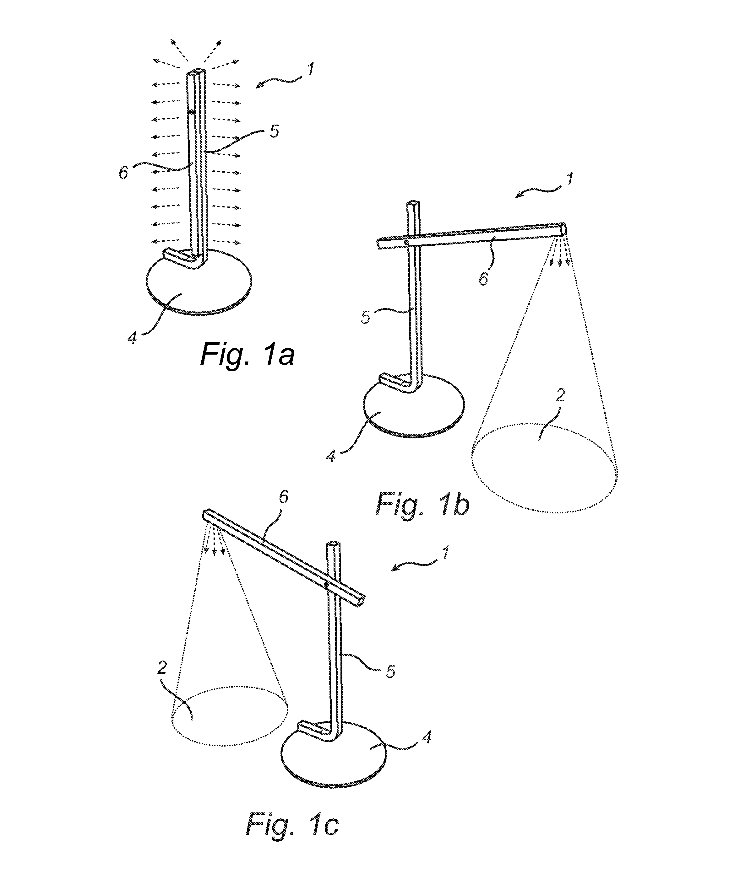
[0035]FIGS. 1a-c schematically illustrate a first exemplary embodiment of the light-output device according to the present invention, in the form of a free-standing table-top lamp 1 providing different light-output functions in the different figures. In FIG. 1a, a “glow” function is provided, in which a large portion of the lamp 1 outputs light having a relatively low intensity and low color temperature, and FIGS. 1b-c show a “task” function for different orientations of the lamp 1. The “task” function may involve outputting light having a relatively high intensity and high color temperature through a small portion of the lamp 1 and directed towards a task area 2.

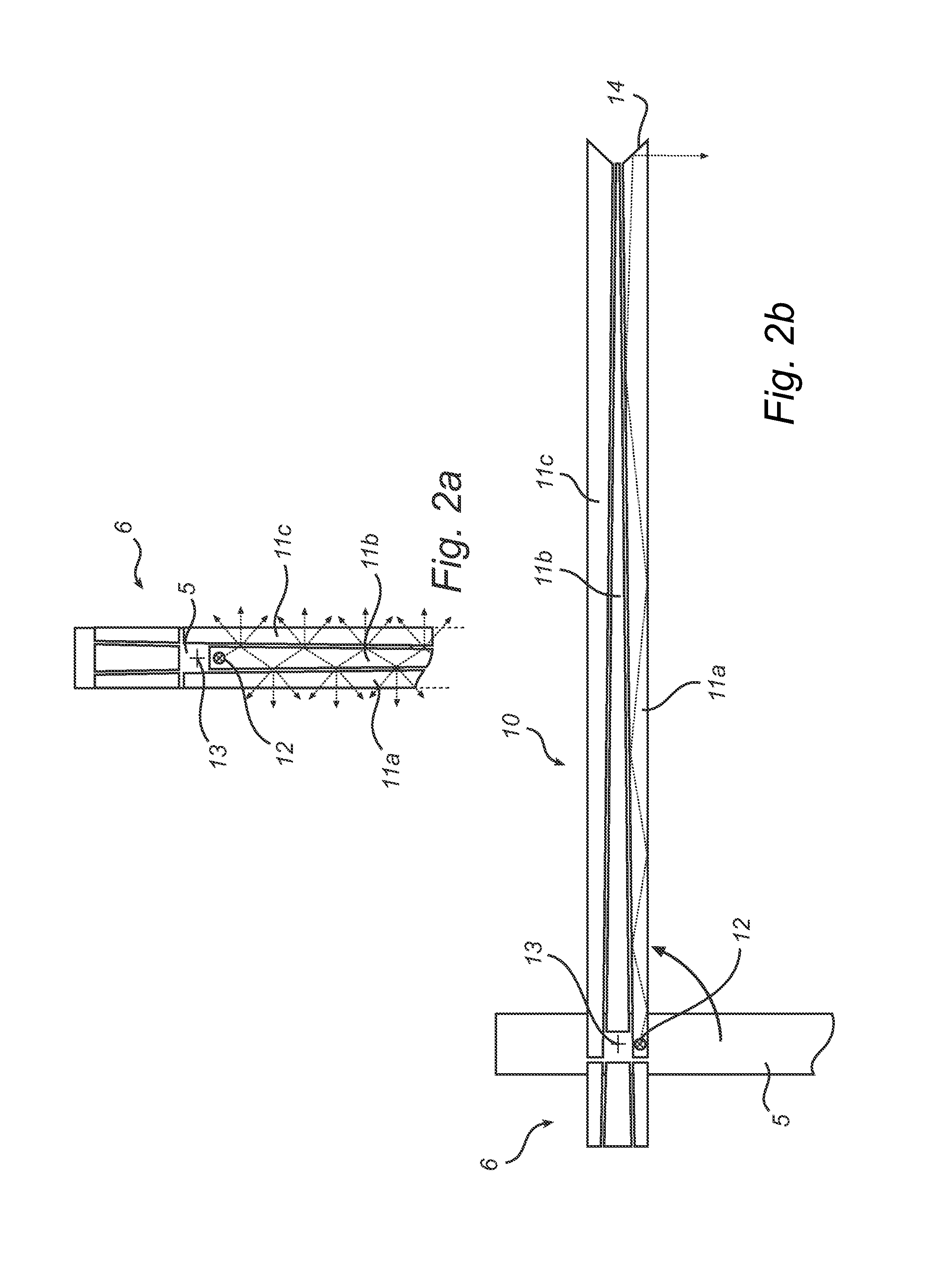
[0036]The lamp 1 in FIGS. 1a-c comprises a plate 4 for keeping the lamp 1 stably standing, a stand 5 attached to the plate 4 and a movable arm 6 that is rotatably connected to the stand 5. As will be described in more detail below, the lamp 1 further comprises a light-source arrangement provided as a part of the stand 5, an...


PUM


Abstract

The invention relates to a light-output device (1; 10; 30) controllable to provide different light-output functions. The light-output device comprises a light-source arrangement (12; 31) configured to emit light; and a light-guiding system (10; 32) arranged to receive the light and configured to guide the light to at least one light-output surface of the light-guiding system. The light-guiding system (10; 32) comprises at least a first light-guide (11b; 37) and a second light-guide (11a; 40, 41); and the light-guiding system (10; 32) is movable relative to the light-source arrangement (12; 31) between at least a first position where light output by the light-source arrangement is guided by the first light-guide (11b; 37) to provide a first light-output function, and a second position where light output by the light-source arrangement is guided by the second light-guide (11a; 40, 41) to provide a second light-out put function, different from the first light-output function. The present invention is based on the realization that different light-output functions conveniently and intuitively can be achieved by moving a light-guiding system comprising at least two light-guides relative to a stationary light-source arrangement. Hereby, different light-output functions can be achieved with a single stationary light-source arrangement.

Description

FIELD OF THE INVENTION[0001]The present invention relates to a light-output device controllable to provide different light-output functions.BACKGROUND OF THE INVENTION[0002]Through the increasing availability of more compact light-sources that may not need to be replaced over the lifetime of a luminaire, new design and functionality has become possible.[0003]For example, it should be possible to provide different lighting functions, such as general illumination and concentrated task lighting using a single light-output device with several sets of light-sources, such as LEDs, that are appropriately arranged and that are individually controllable. However, this might result in a relatively complicated and costly light-output device.SUMMARY OF THE INVENTION[0004]In view of the above-mentioned and other drawbacks of the prior art, a general object of the present invention is to provide an improved light-output device that is controllable to provide different light-output functions.[0005...

Claims


Application Information

Patent Timeline
Patent Type & Authority Applications(United States)
IPC IPC(8): F21V8/00F21K99/00
CPCF21K9/52G02B6/0096F21S6/002F21V14/02F21W2131/301G02B6/0001G02B6/0006G02B6/0031G02B6/0075G02B6/3504F21S6/003F21V14/06F21K9/61F21Y2115/10F21V9/40
Inventor VISSENBERG, MICHEL CORNELIS JOSEPHUS MARIEVAN GORKOM, RAMON PASCALBUKKEMS, PETER JOHANNES MARTINUSVERHOEVEN, MARK JOHANNES ANTONIUSDUIJMELINK, ANDREAS ALOYSIUS HENRICUSDE WILT, MONICA ANTONIA MARIAFOEDERER, RICHARD JOSEPHUS ARNOLDUS MARIA
Owner SIGNIFY HLDG BV
Learn More