Fluid supply apparatus

Active Publication Date: 2014-05-15
SEIKO EPSON CORP
View PDF3 Cites 25 Cited by
  • Summary
  • Abstract
  • Description
  • Claims
  • Application Information

AI Technical Summary

Benefits of technology

The invention is a fluid supply apparatus that provides fluid to a medical device. It includes two pumps, one for sucking in fluid and one for feeding it. The apparatus has a flexible flow path that uses an elastic member to communicate with the pumps. The flow path is designed to deform at specific timings to prevent fluctuations in the fluid flow rate. This results in a more constant and stable supply of fluid to the medical device.

Problems solved by technology

For example, in the case where the technique is applied to a fluid supply apparatus which feeds fluid to a water jet knife as a medical apparatus, a problem is pointed out that a pulsating flow is generated in the fluid ejected from the water jet knife, which is undesirable to the operation of the water jet knife.
Also, various other issues are pointed such as reduction in size of the device, reduction in cost, resource saving, easier manufacturing, and improvement in user-friendliness.
Such problems are equally seen in devices for supplying fluid not only to a water jet knife but also to other medical apparatuses.

Method used


Image

  • Fluid supply apparatus
  • Fluid supply apparatus
  • Fluid supply apparatus

Examples


first embodiment

A. First Embodiment

A1. System Configuration

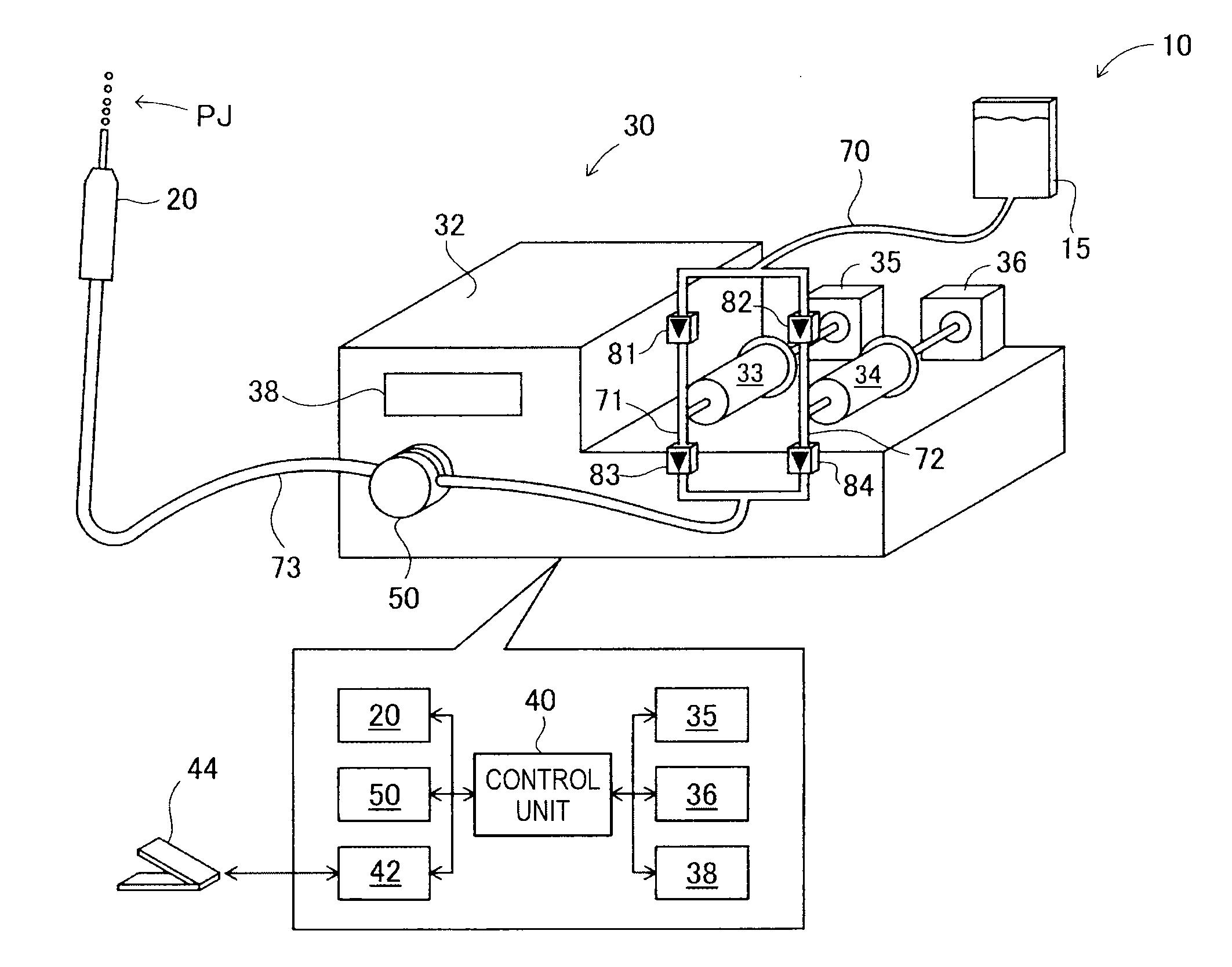
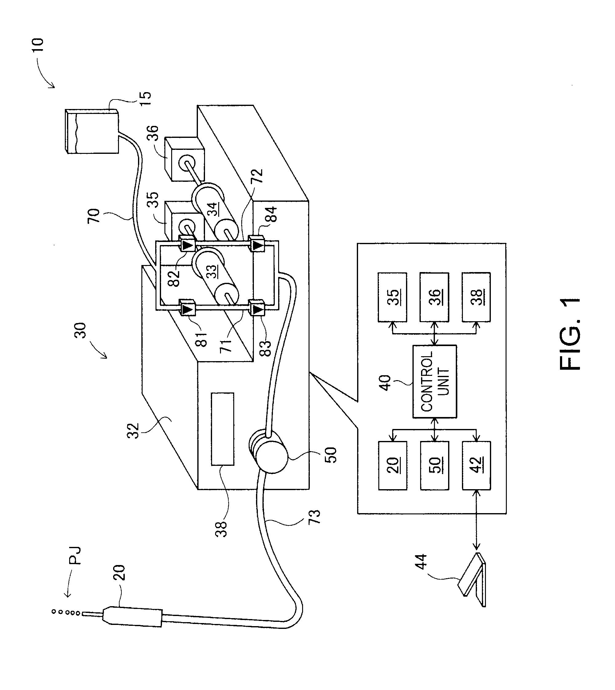
[0030]FIG. 1 is an explanatory view illustrating a water jet knife system 10 using a fluid supply apparatus as a first embodiment of the invention. A water jet knife is a kind of surgical knife and ejects fluid at a high pressure to perform incision and excision with the ejection pressure. In this embodiment, a physiological saline solution, Ringer's solution, water or the like is employed as fluid to be ejected.

[0031]The water jet knife system 10 has a water jet knife 20, a fluid supply apparatus 30 which supplies water to the water jet knife 20, and a fluid storage unit 15 which stores water to be supplied to the water jet knife 20. The water jet knife 20 has, inside itself, a mechanism which generates a pulse water flow using a piezoelectric element as a power source. In the water jet knife 20, the piezoelectric element is driven at a predetermined frequency to eject water supplied from the fluid supply apparatus 30 to outside as a pulse...

modification 1

B1. Modification 1

[0063]In the above embodiments, the fluid supply apparatus 30 has two plunger pumps. However, plunger pumps may be provided in an arbitrary number equal to two or greater, such as three or four, as long as these plunger pumps can be installed in the fluid supply apparatus 30. Also, the timing of the suction operation and the feeding operation of each of the plural plunger pumps is not limited to the timing described with reference to FIGS. 5A to 5C, and various timings can be employed. For example, the timings of the feeding operations of the plural plunger pumps may overlap each other. Even in such a case, the timing of internal pressure fluctuation caused by the feeding operation buy the plunger pumps can be acquired by measurement in advance and the control unit 40 can cause the flow path deforming mechanism 50 to operate according to the acquired timing, to supply water to the water jet knife 20 at a stable flow rate.

[0064]FIGS. 8A to 8C are explanatory views i...

modification 2

B2. Modification 2

[0067]In the above embodiment, the flow path deforming mechanism 50 (FIGS. 3A and 3B, FIGS. 4A and 4B) is employed as a flow path deforming unit. However, various forms can be employed without being limited to the embodiment, as long as the internal pressure in the flow path can be changed by deformation of the flow path. FIGS. 9A to 9C are explanatory views showing a flow path deforming mechanism 50a as an example. The flow path deforming mechanism 50a holds and fixes the flow path 73 between a groove portion 52a and a movable portion 56 (see FIGS. 9A, 9B and 9C). As shown in FIG. 9C, the movable portion 56 is an open / close type. When the movable portion 56 is closed, a lock mechanism 57 (FIG. 9C) locks the movable portion 56.

[0068]As shown in FIG. 9C, the flow path deforming mechanism 50a has a pressing portion 54a and presses the flow path 73 under the control of the control unit 40. The drive mechanism of the pressing portion 54a is the same as the pressing mec...


PUM


Abstract

A fluid supply apparatus which supplies fluid to a medical apparatus includes: a pump mechanism including a first pump capable of a suction operation of the fluid after a feeding operation of the fluid, and a second pump capable of a suction operation of the fluid during the feeding operation and a feeding operation of the fluid during the suction operation; a flow path which includes an elastic member and which communicates with the first pump and the second pump and supplies the fluid to the medical apparatus; and a flow path deforming unit which deforms a part of the flow path. The flow path deforming unit starts first deformation of the flow path before the first pump switches from the feeding operation to the suction operation, and completes the first deformation and starts second deformation of the flow path during the feeding operation by the second pump.

Description

[0001]This application claims priority to Japanese Patent Application No. 2012-248058 filed on Nov. 12, 2012. The entire disclosure of the Japanese Patent Application No. 2012-248058 is hereby incorporated herein by reference.BACKGROUND[0002]1. Technical Field[0003]The present invention relates to a technique for supplying fluid to a medical apparatus.[0004]2. Related Art[0005]According to a related art, for example, a technique disclosed in JP-A-9-264261 is known as a technique for stably feeding fluid. JP-A-9-264261 discloses a technique in which when one of two plunger pumps is carrying out an ejection process at a predetermined ejection pressure, the other stands by in the state of pre-pressurizing the fluid, and when the ejection pressure of the one plunger pump begins to fall, the other starts a pressurization and ejection process of the fluid and raises the pressure to a target ejection pressure within a short time, thus carrying out ejection continuously.[0006]However, in th...

Claims


Application Information

Patent Timeline
IPC IPC(8): A61M5/142A61B17/3203F04B11/00
CPCA61M5/1422F04B11/005A61B17/3203
Inventor UCHIDA, KAZUAKIHIRABAYASHI, ATSUYASETO, TAKESHIMATSUZAKI, TAKAHIRO
Owner SEIKO EPSON CORP
Why Eureka
Try Eureka