Fuel injection control apparatus and method for improving deviation of injector opening time

a control apparatus and fuel injection technology, applied in the direction of electric control, combustion engines, machines/engines, etc., can solve the problems of high pressure injection of the open sensing calculation of the injector in the gdi engine, the same flow rate control between the cylinders becomes difficult, etc., to improve the initial flow rate development behavior of the injector, improve the deviation of the opening time, and improve the effect of the opening tim

Active Publication Date: 2021-03-30
HYUNDAI MOTOR CO LTD +1
View PDF8 Cites 1 Cited by
  • Summary
  • Abstract
  • Description
  • Claims
  • Application Information

AI Technical Summary

Benefits of technology

[0020]Various aspects of the present invention are directed to providing a fuel injection method and apparatus, which may stably improve the performance of the injector by improving the deviation of the opening time for each cylinder even without detecting the opening time point for each cylinder.
[0021]Unlike the related art, the present invention magnetizes a magnetic coil of an injector in advance immediately before injecting fuel without directly determining and estimating the opening time point of the injector for improving the deviation of the opening time point, improving the deviation of the opening time point by facilitating the injector to be opened as fast as possible when the actual injection is performed. According to an exemplary embodiment of the present invention, it is possible to reduce a magnetization time of the coil which is a factor having the greatest effect on the opening time point of the injector, advancing the opening time point of the injector, and accordingly, reducing the deviation of the opening between the injectors.
[0029]A fuel injection control apparatus according to an exemplary embodiment of the present invention for achieving the object is the fuel injection control apparatus including an injector which injects fuel to a cylinder; and a controller which controls the injector so that the fuel is injected from the injector into the cylinder by a target injection amount, and the controller is configured to perform a pre-energizing control in which an injector coil of the injector is magnetized by applying the amount of current having a predetermined magnitude to the injector during a predetermined pre-energizing time to prevent the flow rate of the fuel from being generated, before the main injection in which the target injection amount of the fuel is injected into the cylinder.
[0032]According to an exemplary embodiment of the present invention, it is possible to improve the deviation of the opening time between the standalone injectors even without detecting the injector opening time. Accordingly, even in the case where the injector opening time may not be stably determined because the injector closing time has been incorrectly determined, or the relationship between the injector closing time and the injector opening time may not be specified with respect to all injectors mounted to each of the plurality of cylinders, it is possible to improve the deviation of the injector opening time.
[0033]As a result, the initial flow rate development behavior of the injector may be improved, and the opening time point of the injector may be advanced, effectively performing the low flow rate control. Furthermore, even when the injection time is increased, the injector opening time point becomes constant, and the difference in the opening time points between the standalone injectors may be reduced, effectively performing the low flow rate control in the ballistic section.

Problems solved by technology

That is, the same flow rate control between cylinders becomes difficult.
In recent years, the open sensing calculation of the injector in the GDI engine using high pressure becomes a problem.

Method used


Image

  • Fuel injection control apparatus and method for improving deviation of injector opening time
  • Fuel injection control apparatus and method for improving deviation of injector opening time
  • Fuel injection control apparatus and method for improving deviation of injector opening time

Examples


Embodiment Construction

[0045]Reference will now be made in detail to various embodiments of the present invention(s), examples of which are illustrated in the accompanying drawings and described below. While the present invention(s) will be described in conjunction with exemplary embodiments of the present invention, it will be understood that the present description is not intended to limit the present invention(s) to those exemplary embodiments. On the other hand, the present invention(s) is / are intended to cover not only the exemplary embodiments of the present invention, but also various alternatives, modifications, equivalents and other embodiments, which may be included within the spirit and scope of the present invention as defined by the appended claims.

[0046]Hereinafter, a fuel injection control method and apparatus according to exemplary embodiments of the present invention will be described with reference to the accompanying drawings.

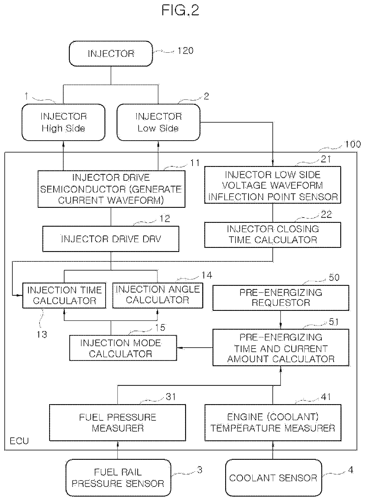
[0047]FIG. 1 is a schematic block diagram of a fuel injection...


PUM


Abstract

A fuel injection control method of injecting fuel to a combustion chamber of an engine through an injector, the method may include pre-energizing to drive the injector during a predetermined pre-energizing time; and performing, by the controller, a main injection in which the injector is controlled by the controller to inject the fuel into the combustion chamber by a target injection amount, after the pre-energizing of the injector, wherein the pre-energizing magnetizes an injector coil of the injector in advance by applying the amount of current preventing the flow rate of the fuel from being generated by the pre-energizing, to the injector during the pre-energizing time.

Description

CROSS-REFERENCE TO RELATED APPLICATION[0001]The present application claims priority to Korean Patent Application No. 10-2020-0018892, filed on Feb. 17, 2020, the entire contents of which is incorporated herein for all purposes by this reference.BACKGROUND OF THE PRESENT INVENTIONField of the Invention[0002]The present invention relates to a fuel injection control apparatus and method, and more particularly, to a fuel injection control apparatus and method, which may improve the deviation of an injector opening time in the low flow rate section of fuel.Description of Related Art[0003]When fuel is supplied to an engine, the supplied fuel amount is determined by a controller (ECU), and the fuel is injected into the engine by an injector by the determined demand amount of fuel to be supplied into the engine.[0004]FIG. 8 illustrates the conventional injector, and a needle valve 120b is formed inside a housing 120a of the injector 120, and an armature 120c, a coil 120d, a spring 120e, and...

Claims


Application Information

Patent Timeline
Patent Type & Authority Patents(United States)
IPC IPC(8): F02D41/38F02D41/40F02D41/24F02D41/22F02D41/20
CPCF02D41/3845F02D41/20F02D41/22F02D41/2441F02D41/402F02D2041/2017F02D2041/226F02D2041/227F02D41/40F02D2041/2003F02D2041/2044F02D2200/021F02D2200/0602Y02T10/40F02D41/221F02D41/2467F02D41/401F02D2041/2048F02D2041/2055F02D2041/389
Inventor HAN, JUNG-SUK
Owner HYUNDAI MOTOR CO LTD
Why Eureka
Try Eureka