Enhanced corrugated filtration pipe dust removing device

An enhanced, dust collector technology, applied in dispersed particle filtration, chemical instruments and methods, gas treatment, etc., can solve problems such as filter tube failure, filter cartridge damage, and difficult to clean particle layer

Pending Publication Date: 2018-05-25
上海境业环保能源科技股份有限公司
View PDF7 Cites 1 Cited by
  • Summary
  • Abstract
  • Description
  • Claims
  • Application Information

AI Technical Summary

Problems solved by technology

[0010] It is made by sintering and solidifying plastic powder and binder in a mold. It has high dust removal efficiency and a long service life of up to 10 years, but the price is high and it is difficult for users to accept it. Currently, it is only used for dust removal in rolling mills in the steel industry.
[0011] At present, paper filter cartridges are usually the most widely used in industrial and mining enterprises, but in actual use, in addition to the use of conventional strong blowing, the filter cartridge will be damaged, and on the other hand, the internal pressure of the filter tube with a thick and short structure will be affected due to diffusion. The serious imbalance of the pressure causes the static and dynamic pressure to be seriously uneven in the whole length of the filter tube, which may lead to the following undesirable situations:
[0012] 1) The dust cleaning in the area with insufficient force is not good, it is easy to cause the particle layer adsorbed and accumulated in the alveolar to be difficult to clean, resulting in continuous increase of filtration resistance and failure of the filter tube;
[0013] The area where the force is too large will easily lead to excessive deformation of the teeth. On the one hand, it may cause the particle layer to envelop the particle layer under the action of the reverse airflow, which will cause difficulty in cleaning due to the deformation of the tooth alveolar; on the other hand, it will cause the top of the tooth alveolar Abnormal damage due to fatigue damage caused by excessive deformation of the root and tooth root, which seriously affects the performance, life, efficiency and economy of the filter tube

Method used


Image

  • Enhanced corrugated filtration pipe dust removing device
  • Enhanced corrugated filtration pipe dust removing device
  • Enhanced corrugated filtration pipe dust removing device

Examples


Embodiment Construction

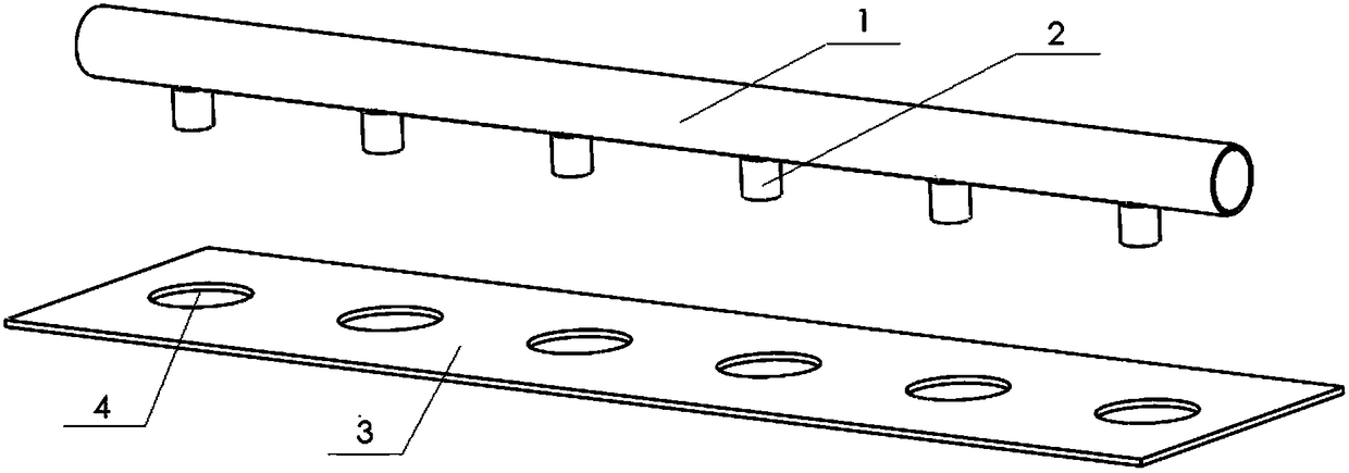
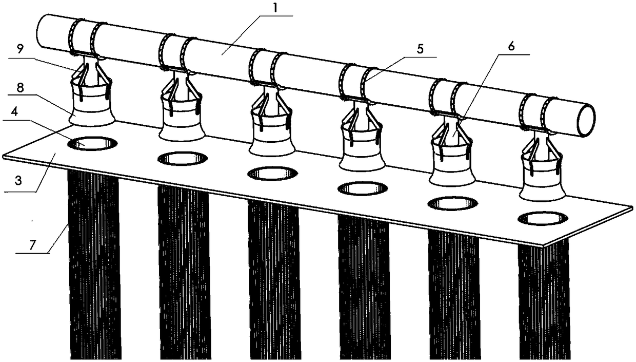
[0050] As shown in the figure, this embodiment discloses an enhanced corrugated filter tube dust collector, which includes a pulse valve arranged on the gas collection box, a blowing main pipe connected to the gas outlet of the gas collecting box, and a blowing main pipe arranged on the blowing main pipe. The blowing device is equipped with a flower plate under the blowing device, the flower plate is provided with an opening corresponding to the blowing device, and the corrugated filter unit is arranged at the opening.

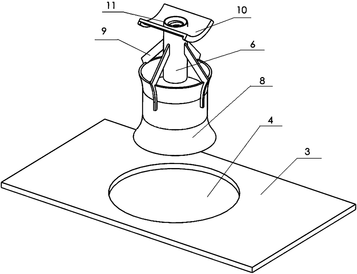
[0051] The blowing device adopts a Venturi blowing pipe, including a blowing main pipe 1, a Venturi nozzle, and a filter cartridge 7. The blowing main pipe 1 is provided with an air outlet, and the upper end of the Venturi nozzle is fixedly arranged on the air outlet. The Venturi nozzle The lower opening of 2 is located above the opening of the filter cartridge 7, and it is characterized in that: the Venturi nozzle includes a housing 8, a jet tube 6 and a reinf...


PUM


Abstract

The invention discloses an enhanced corrugated filtration pipe dust removing device, which comprises a pulse valve arranged on a gas collection box, a blowing main pipe communicated to the gas outletof the gas collection box, and a blowing device arranged on the blowing main pipe, wherein a flower plate is arranged below the blowing device, and is provided with an opening corresponding to the blowing device, and a corrugated filtration unit is arranged at the opening position. According to the present invention, the blowing device uses the Venturi spraying nozzle, and the corrugated filtration unit uses the enhanced corrugated filtration pipe, such that the service life of the product is substantially prolonged, the standardized production can be conveniently achieved, the production efficiency is improved, and the production and maintenance cost can be reduced.

Description

technical field [0001] The invention relates to the technical field of dust removal equipment design, in particular to a corrugated filter tube dust collector. Background technique [0002] In the field of industrial dust removal technology, filter dust collectors are usually used to quickly physically separate dust particles in the air. This filter dust collector usually includes a shell and a blowing device. Including blowing pipe, pulse valve and gas storage tank. The blowing pipe is set at the opening of the filter. When the dust collector works for a period of time, more dust particles will be adsorbed on the filter to affect the filtration efficiency. At this time, the pulse valve is opened and the gas is stored The compressed gas in the tank quickly enters the filter from the blowing pipe to remove the dust particles adsorbed on the surface of the filter. [0003] At present, common industrial filter dust collectors include two categories: bag filter and cartridge fi...

Claims


Application Information

Patent Timeline
Patent Type & Authority Applications(China)
IPC IPC(8): B01D46/24B01D46/52B01D46/00
CPCB01D46/2411B01D46/521B01D2258/06B01D46/58
Inventor 周列杨奡翔
Owner 上海境业环保能源科技股份有限公司
Why Eureka
Try Eureka