Flow rate control valve

a flow rate control and flow rate technology, applied in the direction of valve operating means/releasing devices, functional valve types, transportation and packaging, etc., can solve the problem of achieve the effect of reducing overshoot, preventing and suppressing overshoot of flow ra

Active Publication Date: 2012-06-26
SHIMADZU CORP
View PDF11 Cites 1 Cited by
  • Summary
  • Abstract
  • Description
  • Claims
  • Application Information

AI Technical Summary

Benefits of technology

[0007]The present invention has been accomplished in view of the above problem, and it is an object of the invention to suppress the overshoot of a flow rate when the upstream fluid pressure is abruptly increased.
[0008]To solve the above problem, a pressure compensation type flow rate control valve comprises a spool which is displaced from its initial position by a pressure of fluid entering when an upstream fluid pressure is increased, a first variable orifice whose opening is gradually reduced as the spool is displaced from the initial position, and a second variable orifice whose opening is previously reduced when the spool is in the initial position and whose opening is gradually increased as the spool is displaced from the initial position. With this structure, if the upstream pressure is abruptly increased and the opening of the first variable orifice can not be adjusted in time, it is possible to reduce the flow rate by the second variable orifice and the problem that the flow rate is overshot can effectively be avoided.
[0009]According to the present invention, it is possible to suppress the overshoot of a flow rate when the upstream fluid pressure is abruptly increased.

Problems solved by technology

A problem of the conventional flow rate control valve is that when an upstream fluid pressure is abruptly increased, the flow rate is overshot.

Method used


Image

  • Flow rate control valve
  • Flow rate control valve
  • Flow rate control valve

Examples


Embodiment Construction

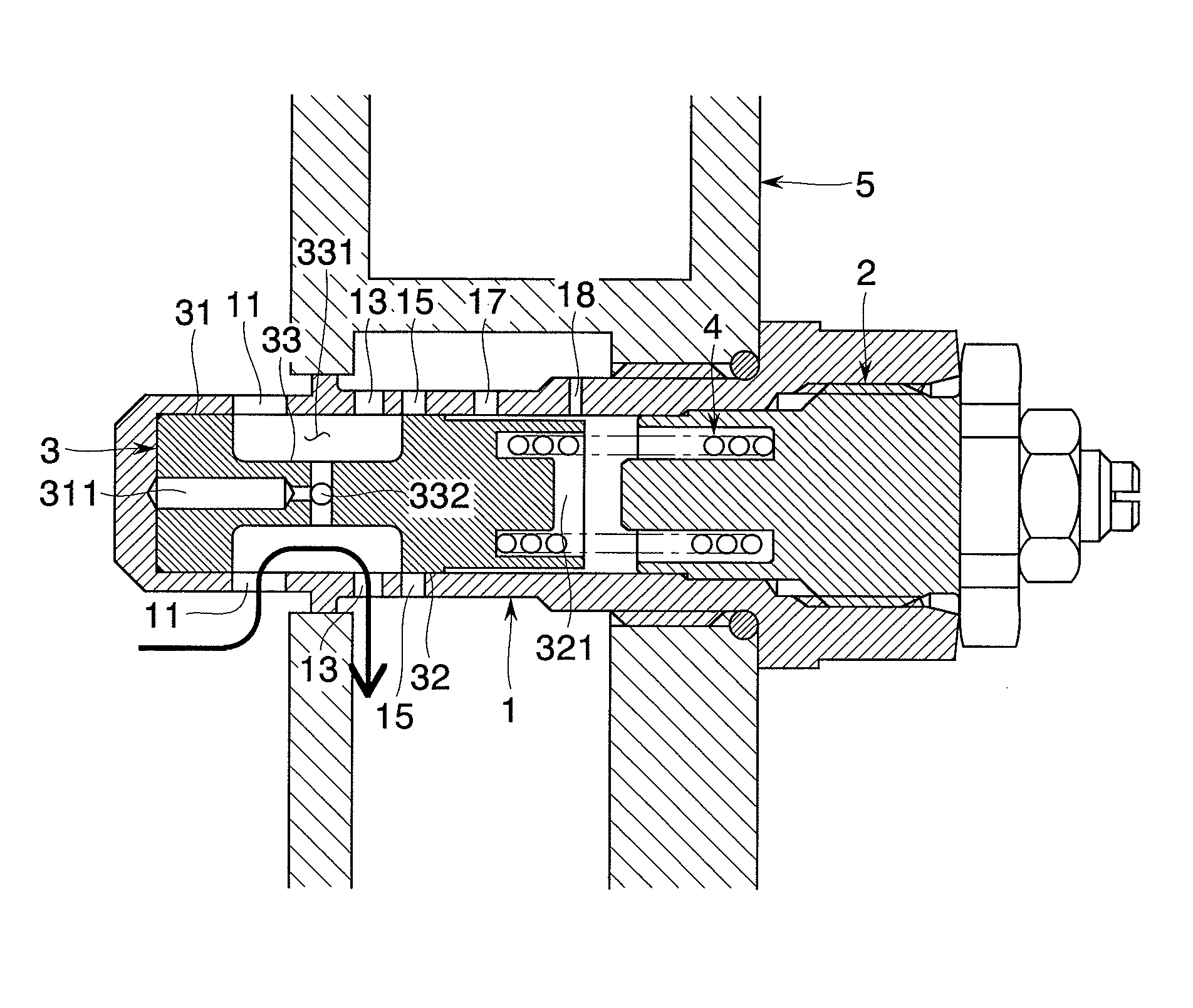
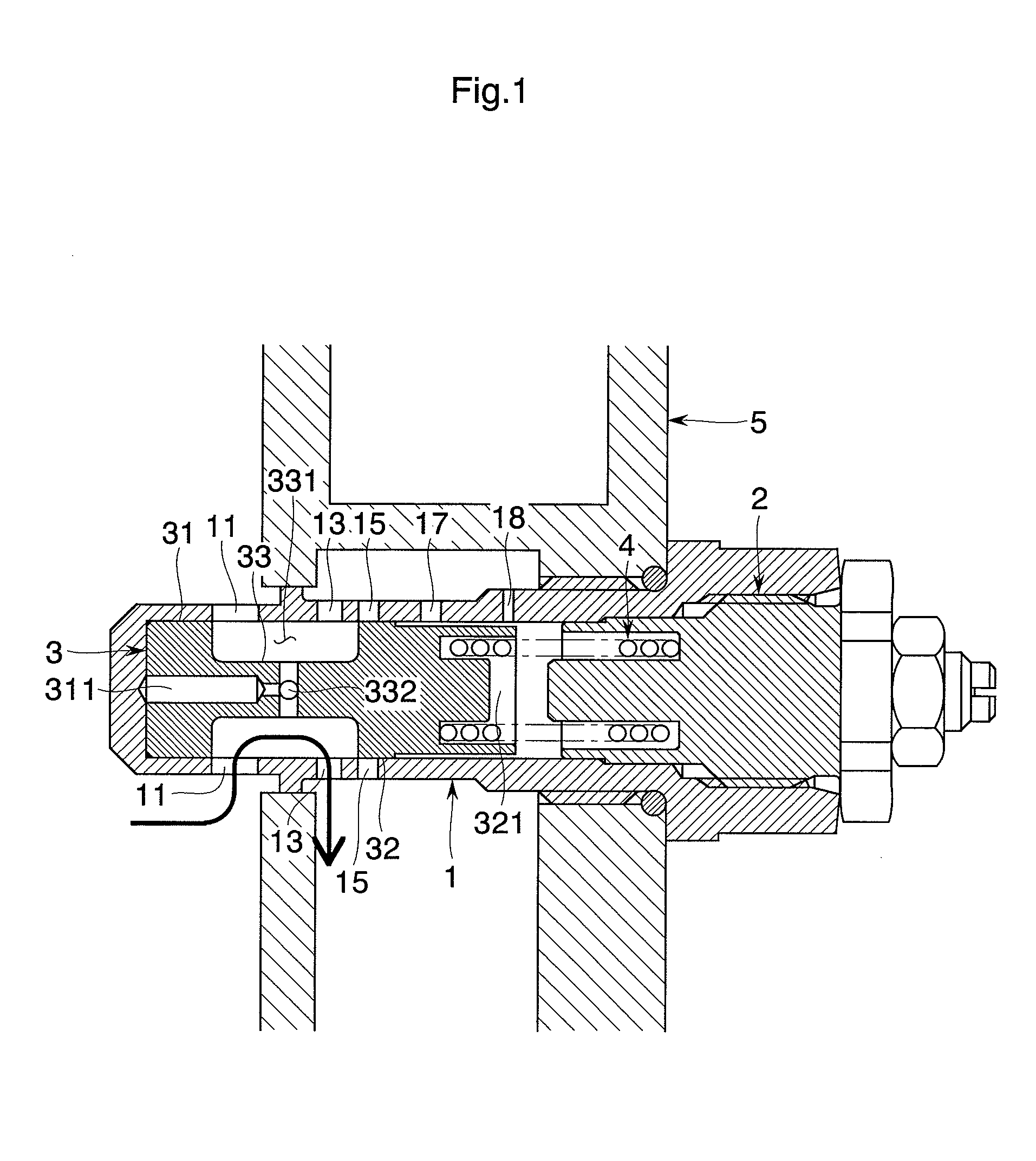
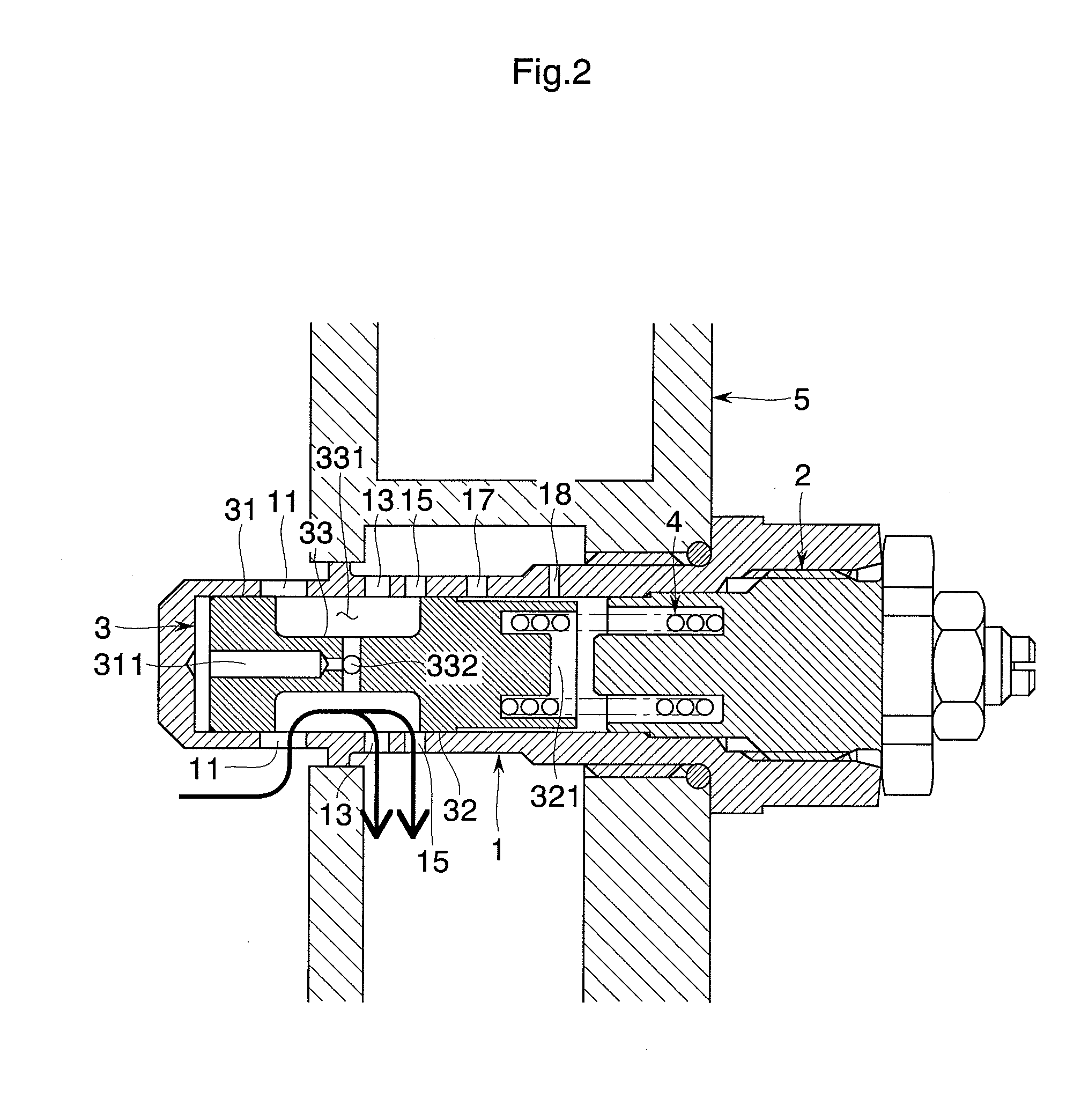
[0014]An embodiment of the present invention will be explained with reference to the drawings. FIGS. 1 and 2 show a flow rate control valve of the embodiment. The flow rate control valve is incorporated in a casing block 5 of a fluid pressure apparatus, and includes a body 1, a plug 2, a control spool 3 and a spring 4 as essential constituent elements.

[0015]The body 1 is of a cylindrical shape whose one end is closed and other end is opened. The spool 3 is held in the body 1 such that the spool 3 can slidably move forward and backward along its axial direction. A plurality of inflow openings 11 and a plurality of outflow openings 13 and 15 are formed in a peripheral wall of the body 1 such that the openings are arranged intermittently substantially on the same circumference. Circulation passages 17 and 18 are also formed in the peripheral wall of the body 1 for introducing downstream fluid pressure into the body 1 (on the other end side in the body 1 where the spring 4 is interposed...


PUM


Abstract

In a pressure compensation type flow rate control valve, overshoot of a flow rate when an upstream pressure is abruptly increased is suppressed. A first variable orifice 11 is provided on the side of an inflow opening and a second variable orifice 15 is provided on the side of an outflow opening. As the spool 3 is displaced from its initial position by a pressure of fluid entering when the upstream fluid pressure is increased, the opening of the first variable orifice 11 is gradually reduced, and the opening of the second variable orifice 15 is gradually increased. Since the second variable orifice 15 on the side of the outflow opening is previously reduced, even if the upstream pressure is abruptly increased, fluid more than a predetermined amount does not flow out toward the downstream.

Description

BACKGROUND OF THE INVENTION[0001]1. Field of Invention[0002]The present invention relates to a flow rate control valve used for a fluid pressure apparatus in various industrial machines and vehicles.[0003]2. Description of Related Art[0004]As a pressure compensation type flow rate control valve capable of maintaining a flow rate constant even if a fluid pressure is varied, one such as disclosed in Japanese Patent Application Laid-open No. 2004-183818 is known. In this flow rate control valve, a control spool is slidably disposed in a cylindrical body, and a spring which resiliently biases the spool in the axial direction is interposed between the body and the spool. An inflow side thereof is a variable orifice whose opening can be varied, and an outflow side thereof is a fixed orifice whose opening cannot be varied.[0005]If the upstream fluid pressure is increased, high pressure fluid flows in and the pressure in a valve chamber is increased, and the spool is displaced against the r...

Claims


Application Information

Patent Timeline
Patent Type & Authority Patents(United States)
IPC IPC(8): F16K31/12
CPCG05D16/10Y10T137/7793Y10T137/7781Y10T137/7811Y10T137/7869Y10T137/7784
Inventor KUROMUSHA, JUNYA
Owner SHIMADZU CORP
Why Eureka
Try Eureka