Magnetic circuit

a magnetic circuit and circuit technology, applied in the field of voice coils, can solve the problems of limiting the capacity of the circuit and reducing the effective pump area of the membrane, and achieve the effect of improving the self-alignment properties of the stack and improving the distribution of magnetic flux

Inactive Publication Date: 2014-05-15
SHENZHEN MINDRAY BIO MEDICAL ELECTRONICS CO LTD
View PDF34 Cites 2 Cited by
  • Summary
  • Abstract
  • Description
  • Claims
  • Application Information

AI Technical Summary

Benefits of technology

[0014]By having a conical shaped interface between the conical magnet and the inner surface of the magnet cup improves the distribution of the magnetic flux in the magnetic circuits.
[0015]Even further, by having all three parts conically shaped improves the self-alignment properties of the stack even further.

Problems solved by technology

If it is too concentrated, the steel will be saturated and not able to conduct any more flux which leads to both leakage of magnetic flux (i.e. immediate magnetic material will be attracted) and limit the circuit's capacity.
The cylindrical design of the magnet cup is also limiting the voice coil to have a mount of its free shaft end outside this cylindrical outer shape.
Further, the deceleration reduces the effective pump area of the membrane closer to the end of a stroke.

Method used


Image

  • Magnetic circuit
  • Magnetic circuit
  • Magnetic circuit

Examples


Embodiment Construction

[0040]Specific examples of the disclosure now will be described with reference to the accompanying drawings. This disclosure may, however, be embodied in many different forms and should not be construed as limited to the embodiments set forth herein; rather, these embodiments are provided so that this disclosure will be thorough and complete, and will fully convey the scope of the disclosure to those skilled in the art. The terminology used in the detailed description of the embodiments illustrated in the accompanying drawings is not intended to be limiting of the disclosure. In the drawings, like numbers refer to like elements.

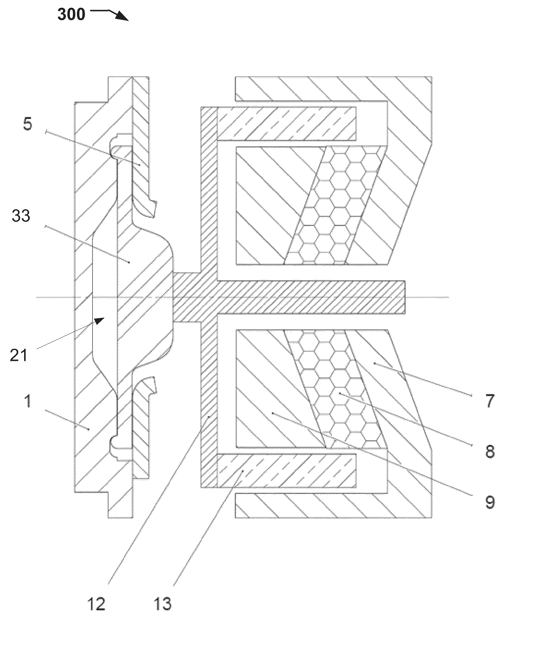
[0041]The following description focuses on an embodiment of the present disclosure applicable to a magnetic circuit and to a voice coil. The voice coil is to be used as an actuator. For example, the voice coil may be used as an actuator for a membrane pump, such as a sampling pump in devices for patient monitoring, breath monitoring, anaesthesia monitoring, e...


PUM

PropertyMeasurementUnit
anglesaaaaaaaaaa
angleaaaaaaaaaa
shapeaaaaaaaaaa

Abstract

A magnetic circuit for a voice coil, comprising, a magnet cup with a one sided open cylindrical shape with a base. The magnetic circuit further includes a conical magnet with a side including a partial conical shape. The magnetic circuit includes a pole shoe which has a side with a recessed conical shape corresponding to the conical shape of said magnet. The magnet cup, the conical magnet and the pole shoe are stacked so that the conical magnet is centrally arranged on the base inside said magnet cup, the pole shoe is arranged on the conical magnet so that the side with a recessed conical shape of the pole shoe is in contact with the side with a conical shape of the conical magnet, such that an air gap is obtained between an inner wall surface of the magnet cup and the stacked conical magnet and the pole shoe.

Description

RELATED APPLICATIONS[0001]The present application claims the benefit under 35 U.S.C. §119(e) of U.S. Provisional Patent Application 61 / 726,962 filed Nov. 15, 2012 titled “PROGRESSIVE PUMP FORCE REGULATION,” U.S. Provisional Patent Application 61 / 726,965 filed Nov. 15, 2012 titled “EXTENDED ELASTICITY OF PUMP MEMBRANE WITH CONSERVED PUMP FORCE,” and U.S. Provisional Patent Application 61 / 727,012 filed Nov. 15, 2012 titled “Magnetic Circuit,” each of which applications is hereby incorporated herein by reference in their entirety.[0002]The present application also claims a priority benefit claims the benefit under 35 U.S.C. §119 of European Patent Application 12192847.7 filed Nov. 15, 2012 titled “PROGRESSIVE PUMP FORCE REGULATION,” European Patent Application 12192859.2 filed Nov. 15, 2012 titled “EXTENDED ELASTICITY OF PUMP MEMBRANE WITH CONSERVED PUMP FORCE,” and European Patent Application 12192889.9 filed Nov. 15, 2012 titled “Magnetic Circuit,” each of which applications is hereb...

Claims


Application Information

Patent Timeline
Patent Type & Authority Applications(United States)
IPC IPC(8): F04B45/047H02K1/34
CPCH02K1/34F04B45/047F04B43/04H02K41/0356Y10T29/49236F04B43/0063
Inventor WERNER, JOHANGABRIELSSON, JOAKIMBOXELL, TORBJORN
Owner SHENZHEN MINDRAY BIO MEDICAL ELECTRONICS CO LTD
Why Eureka
Try Eureka