Permanent magnet motor rotor having magnetic permeable material for enhanced flux distribution

a permanent magnet, flux-enhancing technology, applied in the direction of dynamo-electric machines, magnetic circuit rotating parts, magnetic circuit shape/form/construction, etc., can solve the problems of significant weight and heat dissipation drawbacks, limited output power, backing materials, etc., to achieve enhanced flux distribution, high torque output, and enhanced flux distribution

Inactive Publication Date: 2005-01-18
HANON SYST EFP BAD HOMBURG GMBH
View PDF8 Cites 6 Cited by
  • Summary
  • Abstract
  • Description
  • Claims
  • Application Information

AI Technical Summary

Benefits of technology

n the radial direction, to provide advantageous effects. With this arrangement, flux can be concentrated, with virtually no loss or deleterious transformer interference effects in the electromagnet cores, as compared with prior art embodiments.
The above-identified copending related U.S. patent application of Maslov et al., number 09 / 826,423, describes optimization of rotor parameters such as the grade of the magnets, the energy density and the overall magnetic characteristics of the magnet grade, the size and the dimensions of the magnets. Adjustment of such parameters effect the working permeance and the overall operating condition of the magnet when it is part of the rotor. Other factors are the temperature stability of the magnet, the finishing, coating and post processing steps taken in manufacturing of the magnets for the intended application, the stability of the magnetization over the curvilinear surface of the magnet, uniformity of the radial polarization of the magnet, the adjacent gap between two separate magnets, the mechanical features of the edges of the magnets, and the return flux path of the magnet as provided by a back iron ring section.
The Maslov et al. applications recognize that isolation of the electromagnet groups permits individual concentration of flux in the magnetic cores of the groups, with virtually no flux loss or deleterious transformer interference effects with other electromagnet members. Operational advantages can be gained by configuring a single pole pair as an isolated electromagnet group. Magnetic path isolation of the individual pole pair from other pole groups eliminates a flux transformer effect on an adjacent group when the energization of the pole pair windings is switched. The lack of additional poles within the group avoids any such effects within a group.
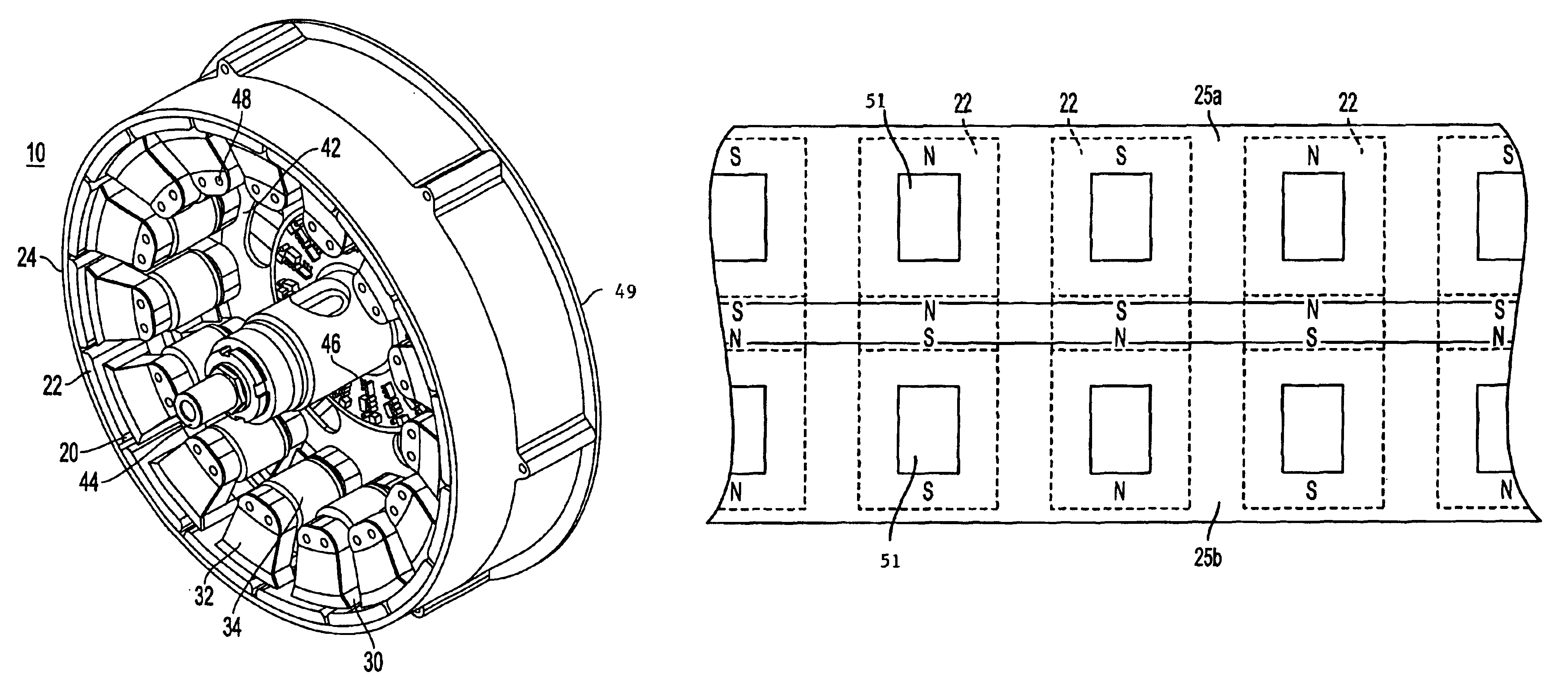
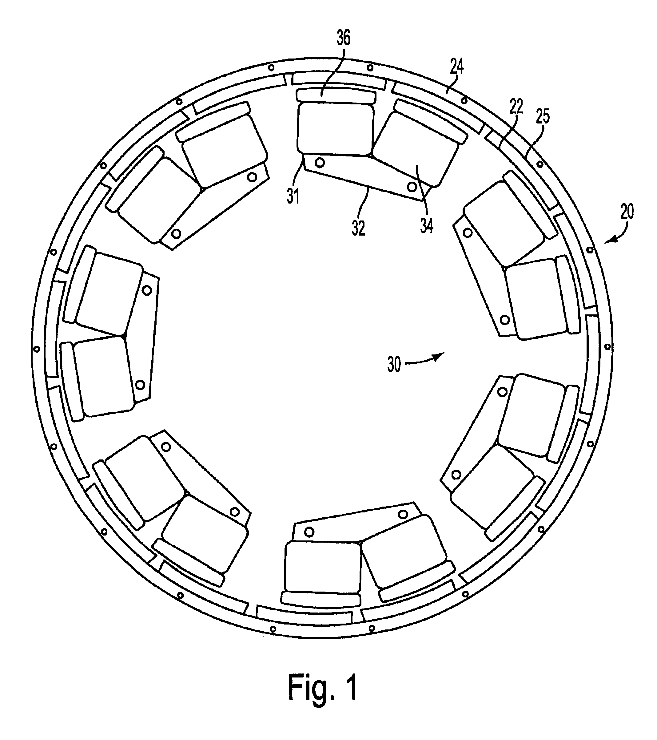
FIG. 1 is a plan view of a motor such as disclosed in the above-identified 09 / 826,423 application. Reference is made to that application for a more detailed description. Rotor member 20 is an annular ring structure having a plurality of permanent magnets 22 substantially evenly distributed. The permanent magnets are divided into groups of north / south pole pairs, the permanent magnets of each group joined by magnetically permeable material 25 that serves as a magnetic return path between the adjacent permanent magnetic poles 22. The permanent magnet groups each form a magnetic circuit that is isolated from adjacent groups. Cylindrical back plate 24, of non-magnetically permeable material such as aluminum, joins the permanent magnet groups to form an annular ring. The permanent magnets alternate in magnetic polarity along the inner periphery of the annular ring. The rotor surrounds a stator member 30, the rotor and stator members being separated by a radial air gap. Stator 30 comprises groups of poles 31 of uniform construction that are evenly distributed along the air gap. Each stator group comprises a generally U-shaped magnetic structure 32 having two pole faces 36 at the air gap. Each stator group structure is separate, and magnetically isolated, from adjacent groups. The legs of the poles are wound with windings 34. The windings, when energized, are configured to provide opposite north / south polarities to the poles of each pole pair, thereby forming an electromagnet. Reversal of polarity of energization effects reversal of the magnetic polarities of the pole pair. Appropriate timed switching of stator winding energization along the radial air gap effects electromotive force generation through interaction of magnetic forces between the stator and rotor across the air gap. Stator groups 31 are secured to non magnetically permeable support structure, not shown herein, whereby the stator groups form an annular ring configuration. A relatively narrow radial stator dimension provides a favorable concentration of flux within each stator element structure focussed at the air gap. By virtue of this configuration, and the absence of stray transformer effects from adjacent stator pole groups, high torque output can be efficiently obtained.
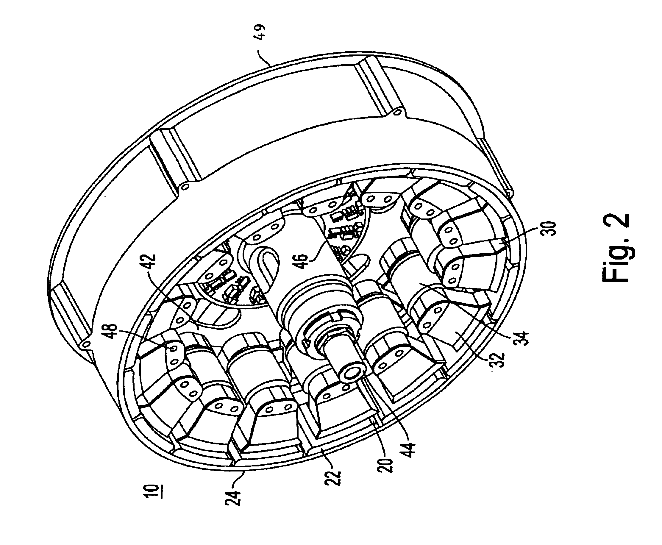
The above-identified U.S. application Ser. No. 09 / 966,101 of Maslov et al. describes benefits to be gained from utilization of three dimensional aspects of motor structure. FIG. 2 is a cutaway view of a structure such as described in that application. Motor 10 comprises annular permanent magnet rotor 20 and annular stator structure 30 separated by a radial air gap. The stator comprises a plurality of ferromagnetically isolated elements. Core segments 32, made of magnetically permeable material and isolated from direct contact with each other, have respective windings 34 formed thereon. The rotor comprises a plurality of permanent magnets 22, circumferentially distributed about the air gap and affixed to a non-magnetic annular back plate 24, which may be formed of aluminum or other non magnetically permeable material. The flux distributions produced by the rotor magnets can be further enhanced by provision of a magnetically permeable element mounted to the back of the rotor magnets. The stationary shaft 44, plates 42 and stator structure, are contained within a housing 49, to which the annular rotor backplate and permanent magnets are attached. Reference is made to the application for a more detailed description.
Also described therein is the further enhancement of flux distributions produced by the rotor magnets by provision of a magnetically permeable element mounted to the back of the rotor magnets, such as illustrated in FIGS. 3a-3d. FIG. 3a illustrates a continuous magnetic annular back plate 25 upon which are mounted the individual permanent magnets. Each axially adjacent pair of magnets 22a and 22b is a rotor permanent magnet pole pair that interacts with a stator core element pole pair to effect motor rotation. A significant increase in the effective flux density in the air gap is obtained without saturation of flux in the back iron. In the illustration of FIG. 3b, the magnetic annular back plate 25 is segmented into strips 27. Attached to each strip is an axially aligned permanent magnet pair. Spacing between the strips provides improved magnetic flux distribution for the respective individual permanent magnet pairs. Direct losses of stray flux and interference, or cross-talk, between adjoining units are minimized because each axial magnetic unit is structurally disjointed. In the rotor arrangement of FIG. 3c, axially magnetized permanent magnets 26 are located between the axially aligned rotor pair magnets 22a and 22b. North-south magnetization orientation of magnets 22a and 22b is in the radial direction. Magnets 22a and 22b are each in contact with one end of magnet 26 to form an individual rotor axial group. Magnet 26 is magnetized in the axial direction to aid concentration and closure of the flux between magnets 22a and 22b. As in FIG. 3a, magnetic annular back plate 25 is continuous. In the rotor arrangement of FIG. 3d, the magnetic annular back plate 25 is segmented. Each back plate strip 27, upon which a rotor axial group is mounted, is separated from an adjacent strip to improve flux distribution.

Problems solved by technology

The progressive improvement of electronic systems, such as microcontroller and microprocessor based applications for the control of motors, as well as the availability of improved portable power sources, has made the development of efficient electric motor drives for vehicles, as a viable alternative to combustion engines, a compelling challenge.
In the employment of motors for driving vehicles, however, available output power is limited by factors such as overall motor weight and heat development during operation.
Magnetically permeable magnet backing material, typically of iron or the like, has significant weight and heat dissipation drawbacks for such motor environments.

Method used


Image

  • Permanent magnet motor rotor having magnetic permeable material for enhanced flux distribution
  • Permanent magnet motor rotor having magnetic permeable material for enhanced flux distribution
  • Permanent magnet motor rotor having magnetic permeable material for enhanced flux distribution

Examples


Embodiment Construction

The motor of the present invention is suitable for use in driving a vehicle wheel of an automobile, motorcycle, bicycle, or the like. The drawing illustrations thus depict motor structure that can be housed within a vehicle wheel, the stator rigidly mounted to a stationary shaft and surrounded by a rotor for driving the wheel. It should be appreciated, however, that the vehicle context is merely exemplary of a multitude of particular applications in which the motor of the present invention may be employed.

FIG. 4a is a plan view of a single rotor permanent magnet ring, such as may be employed in the motor of FIG. 1. The axis of rotation, not shown, about which the magnets are arranged is oriented in the vertical direction. Permanent magnets 22 of alternating north (N) and south (S) polarities are aligned in a circumferential direction on a magnetically permeable backing material 25 and separated from each other by axially aligned spaces 21. The material may be iron, low-carbon steel ...


PUM


Abstract

A permanent magnet motor has rotor structure that includes magnetically permeable backing material attached to magnets for enhancing flux density distribution. A plurality of permanent magnets are circumferentially distributed about an axis of rotation, adjacent magnets successively alternating in magnetic polarity. The magnetically permeable material is configured with apertures therethrough at areas of low flux density, such as at central portions of the magnets, while in contact with perimeter areas of the magnets. Additional apertures in the material may be located at spaced intersections at which no significant flux density exists. The apertures may be replaced with backing material portions of reduced radial thickness.

Description

FIELD OF THE INVENTIONThe present invention relates to permanent magnet electric motors, more particularly to motors having a plurality of permanent magnet rotor elements integrated with magnetically permeable material configured to enhance flux density distribution while minimizing weight.BACKGROUNDThe progressive improvement of electronic systems, such as microcontroller and microprocessor based applications for the control of motors, as well as the availability of improved portable power sources, has made the development of efficient electric motor drives for vehicles, as a viable alternative to combustion engines, a compelling challenge. Electronically controlled pulsed energization of windings of motors offers the prospect of more flexible management of motor characteristics. By control of pulse width, duty cycle, and switched application of a battery source to appropriate stator windings, functional versatility that is virtually indistinguishable from alternating current synch...

Claims


Application Information

Patent Timeline
Patent Type & Authority Patents(United States)
IPC IPC(8): H02K1/27H02K21/22
CPCH02K1/32H02K1/2786H02K1/2791
Inventor MASLOV, BORIS A.SOGHOMONIAN, ZAREH
Owner HANON SYST EFP BAD HOMBURG GMBH
Why Eureka
Try Eureka