Matrix transformer and winding structure

a transformer and matrix technology, applied in the field of matrix transformers, can solve the problems of significant termination loss, significant imbalance in current sharing, termination point between secondary windings and synchronous rectifiers, etc., and achieve the effect of substantially identical electrical characteristics and performance, reduced core weight and volume and/or core loss

Active Publication Date: 2021-02-02
VIRGINIA TECH INTPROP INC
View PDF13 Cites 1 Cited by
  • Summary
  • Abstract
  • Description
  • Claims
  • Application Information

AI Technical Summary

Benefits of technology

[0020]FIGS. 7A and 7B illustrate arrangements of a two core matrix transformer that demonstrate that the matrix transformer of FIG. 5A is electrically identical to the transformers of the matrix transformer of FIG. 4 but do not achieve the meritorious effects of the invention,
[0021]FIGS. 8A and 8B illustrate the improvement in magnetic flux distribution and reduction of flux density achieved by the invention,
[0022]FIG. 9 is an oblique view of an alternative form of the magnetic core structure in accordance with the invention and preferred for some applications, and
[0023]FIGS. 10A, 10B, 10C and 10D are plan view of winding layouts suitable for implementation on four printed circuit board (PCB) layers or four layers of a PCB integrated winding structure.DETAILED DESCRIPTION OF A PREFERRED

Problems solved by technology

While, in theory, the parallel secondary windings and parallel synchronous rectifiers (SRs) can provide total currents well in excess of the current tolerance and ratings of the individual coils and synchronous rectifiers, small differences in electrical properties of these elements, in practice, can cause significant imbalances in current sharing as alluded to above.
Further, in such a topology, termination points between the secondary windings and the synchronous rectifiers are unavoidable, at which the high frequency and high di / dt AC currents cause significant termination losses.
The physical separation of the parallel secondary windings also makes the leakage inductances of the secondary windings significant and unavoidable; causing large winding losses.
The primary drawback of such a DC / DC converter design is the volume of the separate identical transformers comprising the matrix transformer which have separate primary and secondary windings and cores.
Regardless of the core portion shapes, the location where the portions abut each other results in at least a small air gap which, while small, is difficult to achieve uniformity of size; affecting flux, flux density and leakage.
Such irregular shapes cannot be nested together in a particularly compact form and the number of cores increases the weight of the matrix transformer.
It is also difficult to achieve uniformity of air gaps which affect the magnitude of magnetic flux generated by primary winding current when the core is comprised of plural portions.
Additionally, it is difficult to assemble cores and windings (e.g. with a single turn secondary winding for each core) which are oriented as illustrated in FIG. 4.
The cores are not unitary and magnetic coupling between cores may also be a source of non-uniformity of transformers of the matrix transformer constituted in such a manner.
It will be noted that FIG. 6 is identical to that of FIG. 2 except for the illustration of coupling between all transformers in FIG. 6 whereas the respective transformers are not illustrated as being coupled to each other in FIG. 2 and, in fact, any coupling will be incidental due to proximity or core and coil configuration and thus unpredictable.
However, there is no functional change achieved by doing so since the respective cores are not significantly coupled magnetically.
While the number of cores is reduced and the arrangement possibly made slightly more compact by the rearrangement of FIG. 4 to that of FIG. 7A, that reduction requires substantially increased complexity of the primary winding construction and connection while no functional, electrical or magnetic change is achieved.

Method used


Image

  • Matrix transformer and winding structure
  • Matrix transformer and winding structure
  • Matrix transformer and winding structure

Examples


Embodiment Construction

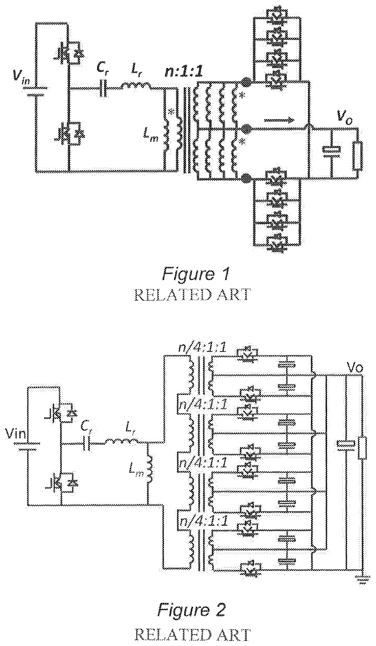
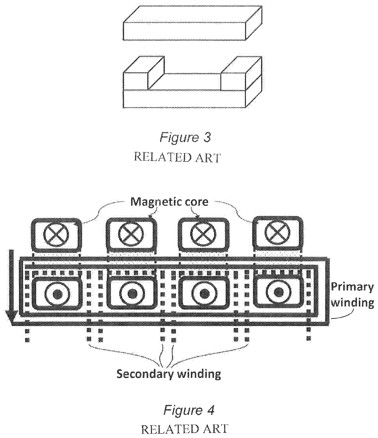
[0024]Referring now to the drawings, and more particularly to FIG. 1, there is schematically shown a conventional design of a DC / DC converter for a large voltage step-down, high current application. It should be appreciated that the power converter design illustrated in FIGS. 1 and 2 and the design of FIGS. 3 and 4 are generalized and arranged to facilitate an understanding of the problems addressed by the invention and are not admitted to be prior art as to the present invention. These Figures have thus been labeled “Related Art”. Also, for convenience and clarity, the illustration and discussion of both the related art of FIGS. 1-4 and the following discussion of the invention will assume a division of the high current portion of the power converter into four branches while any number of separate parallel branches can be provided as the load requirements and the cost of electrical elements having a given current capacity and rating may dictate. Further, for clarity and convenience...


PUM

PropertyMeasurementUnit
magneticaaaaaaaaaa
electrical resistanceaaaaaaaaaa
conduction lossesaaaaaaaaaa

Abstract

A matrix transformer particularly suited to large voltage step-down, high current applications achieves increased good current sharing uniformity or air gap and electrical characteristics and reduced or eliminating termination losses, core losses and winding losses with a unitary magnetic core structure featuring sheets of magnetic material and a two-dimensional array of pillars on which windings, oriented in opposite directions on pillars that are adjacent in orthogonal directions, can be formed or placed comprising metallization on or embedded in a printed circuit board (PCB) structure. Magnetic flux density is reduced by at least one-half by dividing the magnetic flux in each pillar into two paths of increased width in the sheets of magnetic material. Magnetic flux density may be further decreased and flux uniformity improved by extending the sheets of magnetic material beyond a periphery defined by the pillar array.

Description

CROSS-REFERENCE TO RELATED APPLICATIONS[0001]This application claims benefit of priority of U.S. Provisional Application 62 / 454,328, filed Feb. 3, 2017, which is hereby incorporated by reference in its entirety.FIELD OF THE INVENTION[0002]The present invention generally relates to transformers for supplying power to electronic devices and, more particularly, to so-called matrix transformers for large voltage step-down, high current power converter applications.BACKGROUND OF THE INVENTION[0003]While electrical power is usually distributed from the location at which it is generated to the location at which it is utilized as high voltage alternating current (AC) in order to limit transmission infrastructure cost and transmission losses, most electrically powered devices other than electric motors present loads requiring low voltage, direct current (DC) power, often at a closely regulated voltage. While the voltage used for AC power transmission can be easily reduced to lower voltage al...

Claims


Application Information

Patent Timeline
Patent Type & Authority Patents(United States)
IPC IPC(8): H01F17/04H01F27/245H01F27/28H02M3/335H01F27/30H02M3/28H02M3/337H01F27/38H01F38/00
CPCH01F27/245H01F27/2804H01F27/306H02M3/285H02M3/3376H02M3/33523H02M3/33592H01F27/38H01F2027/2809H01F2027/2819H01F2038/006Y02B70/10H02M3/003
Inventor FEI, CHAOLEE, FRED C.LI, QIANG
Owner VIRGINIA TECH INTPROP INC
Why Eureka
Try Eureka