Magnetic coupling mechanism and compensating circuit design for wireless charging of electric vehicle

A wireless charging, electric vehicle technology, applied in electric vehicle charging technology, electric vehicles, charging stations, etc., can solve problems such as wireless power transmission that is difficult to provide high power, power limitation of wireless power transmission, and increase of wireless power transmission distance. , to achieve the effect of improving magnetic flux distribution, strong magnetic coupling ability, and increasing transmission distance

Pending Publication Date: 2022-03-11
袁志鹏
View PDF0 Cites 0 Cited by
  • Summary
  • Abstract
  • Description
  • Claims
  • Application Information

AI Technical Summary

Problems solved by technology

Due to the large height between the tires of the car and the ground, there is a large transmission air gap in the wireless system, and the transmission power of wireless energy is further limited
[0006] Generally, the magnetic coupling capability of the coil is enhanced by increasing the size of the transmitting-receiving coil and changing its shape, but in practical applications, the size of the coil is easily limited by the surrounding environment
[0007] In order to increase the distance of wireless power transmission, relay coils are generally added on the transmitting side and the receiving side. With the increase in the number of relay coils, additional losses will be brought to the system, and it is difficult to provide high-power wireless power transmission.
[0008] In view of the above reasons, traditional magnetic coupling mechanisms and compensation topology circuits are difficult to apply wireless charging to the field of electric vehicle charging with long-distance, high offset, and high power requirements.

Method used


Image

  • Magnetic coupling mechanism and compensating circuit design for wireless charging of electric vehicle
  • Magnetic coupling mechanism and compensating circuit design for wireless charging of electric vehicle
  • Magnetic coupling mechanism and compensating circuit design for wireless charging of electric vehicle

Examples


Embodiment Construction

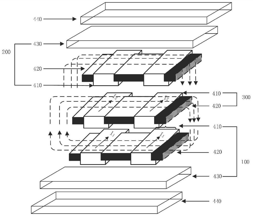
[0032] The present invention will be described in detail below in conjunction with the accompanying drawings and specific embodiments. This embodiment is carried out on the premise of the technical solution of the present invention, and detailed implementation and specific operation process are given, but the protection scope of the present invention is not limited to the following embodiments.

[0033] Such as figure 1 As shown, the metal shielding plate 440 is placed on the outermost side, the transmitting module 100 and the receiving module 200 both include an inductance coil 410, a magnetic core 420, and an insulating plate 410, and the relay module 300 includes an inductance coil 410 and a magnetic core 420; the inductance coil 410 is It is composed of two separate windings, the separate winding is made of multiple litz wires wound in parallel; the magnetic core 420 adopts a rectangular ferrite structure; the metal shielding plate 440 is made of aluminum material, which i...


PUM


Abstract

The invention discloses a magnetic coupling mechanism and compensation circuit design for wireless charging of an electric vehicle, the magnetic coupling mechanism comprises a transmitting module, a relay module and a receiving module, the transmitting module is arranged at the ground end, the receiving module is arranged at the bottom of a vehicle body, and the transmitting module and the receiving module are respectively composed of a metal shielding plate, an insulating plate, an inductance coil and a magnetic core; the relay module is arranged between the transmitting module and the receiving module and consists of an inductance coil and a magnetic core; two separated coil windings of the transmitting module, the relay module and the receiving module are spirally wound on two sides of a magnetic core; the invention further comprises a compensation topology circuit structure composed of the active relays. The transmitting side adopts an LCC compensation circuit, a relay coil compensation circuit adopts series compensation, in order to improve the system performance, a relay coil is energized, and a power supply of the relay coil is the same as an inverter power supply of a transmitting coil; and the receiving side adopts LCC compensation. According to the invention, the transmission power of the system is improved, the anti-offset capability of the system is enhanced, and the transmission distance of wireless electric energy is increased.

Description

technical field [0001] The invention relates to the technical field of wireless power transmission, in particular to a magnetic coupling mechanism and compensation circuit design for wireless charging of electric vehicles. Background technique [0002] Wireless Power Transfer (WPT) uses the principle of electromagnetic induction to transmit electric energy from the primary side to the secondary side through the air medium, with the advantages of no contact sparks, small footprint, and strong environmental adaptability. It is widely used in various fields, such as mobile phone electronics, medical equipment, electric vehicles, robots, etc. Among them, wireless charging not only reduces the size of the vehicle battery, but also has stronger flexibility in the charging process, and has a better development prospect. [0003] At present, there are still some shortcomings in the application of wireless power transmission technology to electric vehicle charging: [0004] During t...

Claims


Application Information

Patent Timeline
Patent Type & Authority Applications(China)
IPC IPC(8): B60L53/12H02J50/12H02J50/70
CPCB60L53/12H02J50/12H02J50/70Y02T10/70Y02T10/7072Y02T90/14Y02T90/16
Inventor 袁志鹏
Owner 袁志鹏
Why Eureka
Try Eureka