Method of determining pump flow in rotary positive displacement pumps

a technology of positive displacement and pump flow, which is applied in the direction of liquid fuel engines, process and machine control, instruments, etc., can solve the problems of reducing the theoretical displacement, the inability of the positive displacement pump to operate at closed, and the inability of the positive displacement pump to operate, so as to reduce the slippage and restore the flow accuracy

Inactive Publication Date: 2014-05-15
ITT MFG ENTERPRISES LLC
View PDF7 Cites 14 Cited by
  • Summary
  • Abstract
  • Description
  • Claims
  • Application Information

AI Technical Summary

Benefits of technology

[0013]Published performance for certain types of rotary positive displacement pumps such as progressive cavity pumps have been found to differ from actual performance based on anticipated wear in the stator liner. The published performance for these types of pumps is more indicative of the midpoint in wear then the “as new” pump performance. FIGS

Problems solved by technology

A positive displacement pump cannot be operated at closed valve condition without pressure relief valves or bypass piping as the pump will continue to increase pressure and power until either a shaft or gear breaks or rupture occurs either in the system piping or pump casing.
Therefore, Mr. Henyan's technique is applicable to centrifugal pumps only and cannot be applied to positive displacement pumps.
A positive displacement pump cannot be operated at closed valve condition without a pressure relief valve or bypass piping as it will continue to increase pressure and power until either a shaft or gear breaks or rupture occurs either in the system piping or pump casing.
There is slip which occurs which

Method used


Image

  • Method of determining pump flow in rotary positive displacement pumps
  • Method of determining pump flow in rotary positive displacement pumps
  • Method of determining pump flow in rotary positive displacement pumps

Examples


Embodiment Construction

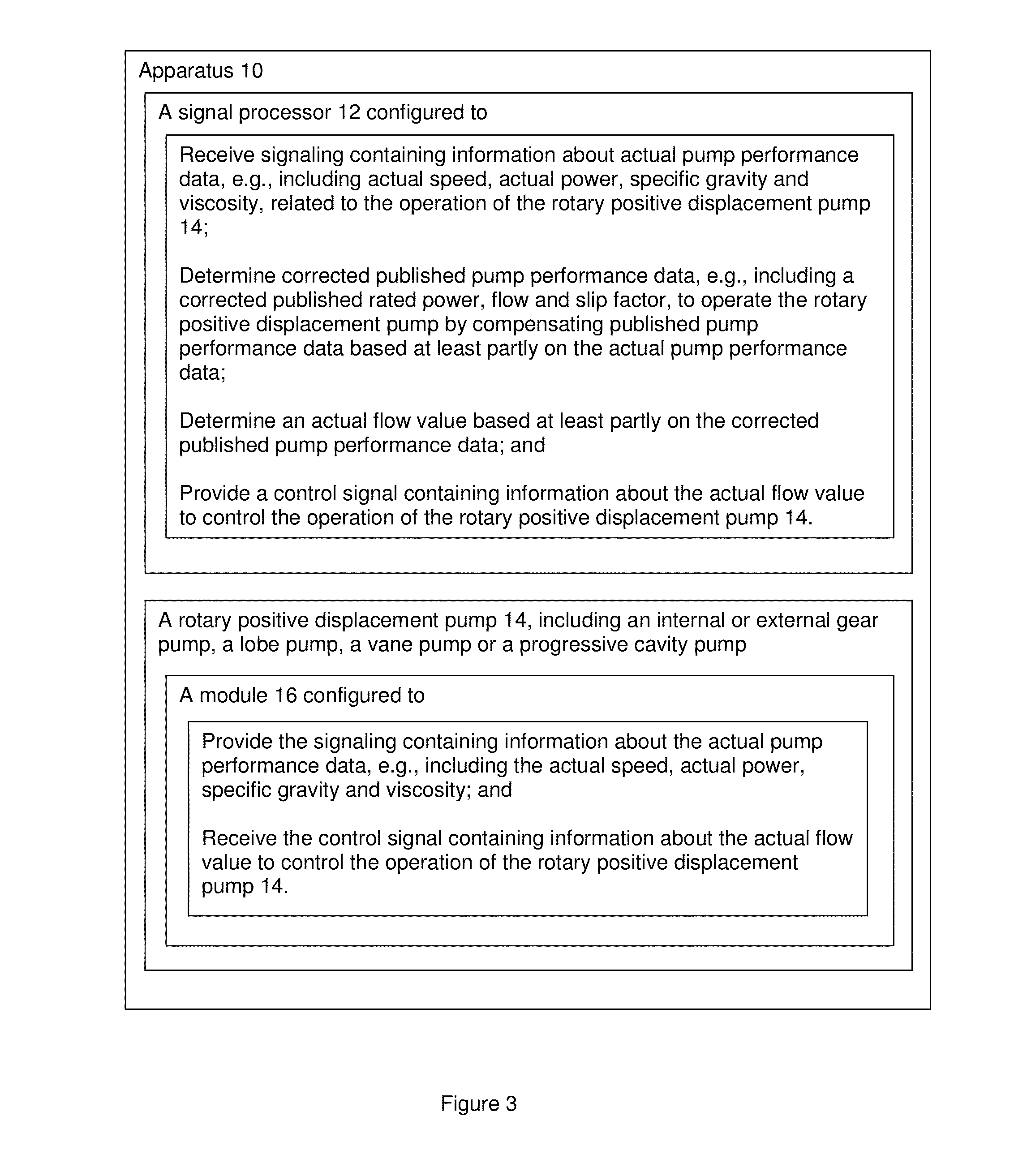
[0069]By way of example, as shown in FIG. 3, according to some embodiments, the present invention may take the form of apparatus 10 that includes a signal processor 12 that may be configured to control and protect the operation of a rotary positive displacement pump 14, e.g., which may include, or take the form of, an internal or external gear pump, a lobe pump, a vane pump or a progressive cavity pump.

[0070]The signal processor 12 may be configured to receive signaling containing information about actual pump performance data related to the operation of the rotary positive displacement pump 14 and determine corrected published pump performance data to operate the rotary positive displacement pump by compensating published pump performance data based at least partly on the actual pump performance data.

[0071]The signal processor 12 may also be configured to determine an actual flow value for the rotary positive displacement pump based at least partly on the corrected published pump p...


PUM


Abstract

Techniques are provided for tuning a rotary positive displacement pump. The techniques include apparatus featuring a signal processor configured to the present invention may take the form of apparatus comprising a signal processor that may be configured to receive signaling containing information about actual pump performance data related to the operation of a rotary positive displacement pump; and determine corrected published pump performance data to operate the rotary positive displacement pump by compensating published pump performance data based at least partly on the actual pump performance data. The corrected published pump performance data may include a corrected published rated power, flow and slip factor, and the actual pump performance data contains information about actual power, specific gravity and viscosity related to the operation of the rotary positive displacement pump and received from a pump controller or controlling device, including a variable frequency drive.

Description

CROSS REFERENCE TO RELATED APPLICATIONS[0001]This application claims benefit to provisional patent application Ser. No. 61 / 623,155, filed 12 Apr. 2012, which is hereby incorporated by reference in its entirety.BACKGROUND OF THE INVENTION[0002]1. Field of the Invention[0003]This application relates to a rotary positive displacement (PD) pump, such as an internal or external gear pump, a lobe pump, a vane pump or a progressive cavity pump; and more particularly, relates to techniques for tuning such a rotary PD pump in order to determine pump flow.[0004]2. Brief Description of Related Art[0005]Many different type or kinds of pumps, including rotary positive displacement pumps, are known in the art. By way of example, some known pumps and shortcomings associated with the same are set forth below:[0006]U.S. Pat. No. 6,591,697, entitled “Method for Determining Pump Flow Rates Using Motor Torque Measurements,” which is hereby incorporated by reference in its entirety, discloses a methodol...

Claims


Application Information

Patent Timeline
IPC IPC(8): G05D7/06G01F25/00
CPCG01F25/0007G05D7/0635F04C14/28F04C2/1071F04C2270/052F04C2270/03F04C2270/02F04C2270/80G01F25/10
Inventor STAVALE, ANTHONY E.
Owner ITT MFG ENTERPRISES LLC
Why Eureka
Try Eureka