Heat treatment apparatus and method of obtaining toner

a technology of heat treatment apparatus and toner, which is applied in the direction of lighting and heating apparatus, furniture, instruments, etc., can solve the problem of difficult uniform heat treatment of powder particles

Inactive Publication Date: 2014-05-22
CANON KK
View PDF0 Cites 40 Cited by
  • Summary
  • Abstract
  • Description
  • Claims
  • Application Information

AI Technical Summary

Benefits of technology

[0012]According to the present invention, it is possible to obtain toner containing fewer coarse particles due to coalescence and having a sharp particle size distribution. Further, it is possible to obtain toner having a circularity distr...

Problems solved by technology

However, in a conventional heat treatment apparatus, the quantity of heat which powder particles receive varies depending u...

Method used


Image

  • Heat treatment apparatus and method of obtaining toner
  • Heat treatment apparatus and method of obtaining toner
  • Heat treatment apparatus and method of obtaining toner

Examples


example 2

of a Heat Treatment Zone Ring

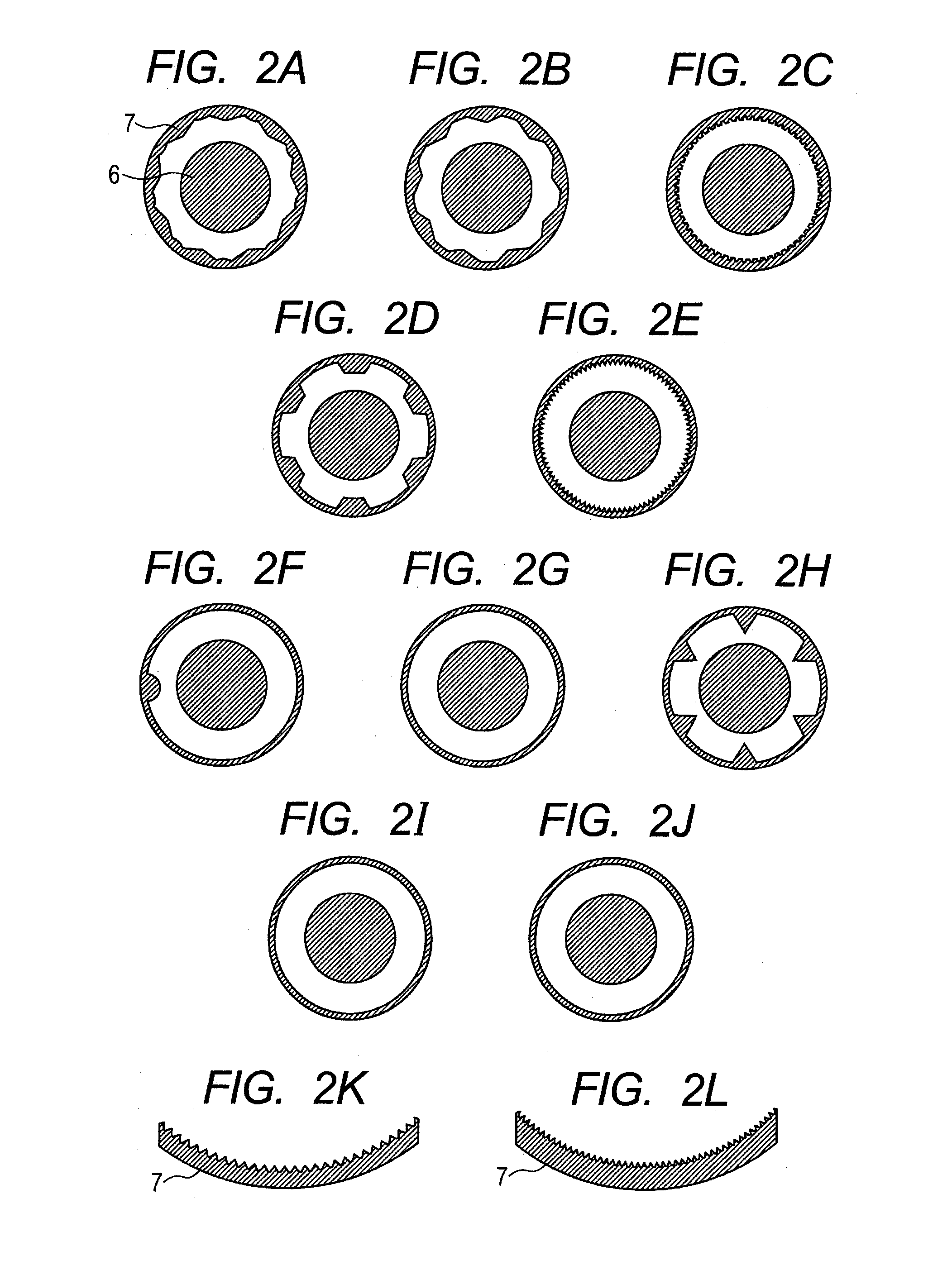
[0115]A ring obtained by providing 9 triangle protrusions each having a height of 20 mm and a length of 200 mm at an equal interval to a cylindrical ring having an inner diameter (diameter) of 500 mm and a height of 300 mm as a base was defined as a ring B. The repetition distance on the circumference of the protrusions was 174.5 mm. FIG. 2B illustrates a schematic cross-sectional view of the ring B and the regulating unit.

example 3

of a Heat Treatment Zone Ring

[0116]A ring obtained by providing 60 round protrusions each having a height of 10 mm and a length of 200 mm at an equal interval to a cylindrical ring having an inner diameter (diameter) of 500 mm and a height of 300 mm as a base was defined as a ring C. The repetition distance on the circumference of the protrusions was 26.2 mm. FIG. 2C illustrates a schematic cross-sectional view of the ring C and the regulating unit.

example 4

of a Heat Treatment Zone Ring

[0117]A ring obtained by providing 6 trapezoid protrusions each having a height of 35 mm and a length of 200 mm at an equal interval to a cylindrical ring having an inner diameter (diameter) of 500 mm and a height of 300 mm as a base was defined as a ring D. The repetition distance on the circumference of the protrusions was 261.8 mm. FIG. 2D illustrates a schematic cross-sectional view of the ring D and the regulating unit.


PUM

PropertyMeasurementUnit
Lengthaaaaaaaaaa
Lengthaaaaaaaaaa
Distanceaaaaaaaaaa

Abstract

A heat treatment apparatus for heat-treating powder particles each containing a binder resin and a colorant includes: a powder particle supply unit (3); a hot air supply unit (2); a cold air supply unit (4); a regulating unit (6); and a collection unit (5). The apparatus is characterized in that: a protrusion with a height of 2 mm or more and 50 mm or less is provided in a region on a downstream side of the powder particle supply unit and on an upstream side of the cold air supply unit in an inner wall surface of the treatment chamber; and the heat treatment apparatus has a cross-section plane, which is perpendicular to a center axis of the treatment chamber and situated at the region where the protrusion is provided, and Dmin and Dmax satisfy the following relation 0.50≦Dmin/Dmax<1.0 where, Dmin represents a minimum value of the distance of a gap between the treatment chamber and the columnar member measured in the cross-section plane, and Dmax represents a maximum value of the distance of a gap between the treatment chamber and the columnar member measured in the cross-section plane.

Description

TECHNICAL FIELD[0001]The present invention relates to a heat treatment apparatus for obtaining toner to be used in an image forming method such as an electrophotographic method, an electrostatic recording method, an electrostatic printing method, or a toner jet system recording method, and to a method of obtaining toner using the apparatus.BACKGROUND ART[0002]In order to obtain toner with an appropriate circularity, there has been proposed a heat treatment apparatus for heat-treating pulverized toner to spheroidize the toner appropriately. However, in a conventional heat treatment apparatus, the quantity of heat which powder particles receive varies depending upon the position through which the powder particles pass, and hence it is difficult to heat-treat the powder particles uniformly.[0003]In order to overcome the problem, a heat treatment apparatus has been proposed, in which a raw material supply portion is provided at the center of the apparatus, and a hot air supply portion i...

Claims


Application Information

Patent Timeline
IPC IPC(8): G03G9/08F26B17/12F26B17/10
CPCG03G9/0815F26B17/124F26B17/103F28C3/12F28F13/06F28F13/12G03G9/081G03G9/0819G03G9/0827G03G9/08755
Inventor TAKENAKA, KOHJIMIZO, YUICHIMINAGAWA, HIRONORIKOBORI, TAKAKUNIOHTSU, TAKESHIHAGIWARA, JUNICHIITO, DAISUKEKAWAKITA, KUNIHIKO
Owner CANON KK
Why Eureka
Try Eureka