Ultrasound transducer assembly and method of manufacturing the same

a transducer and ultrasonic technology, applied in ultrasonic/sonic/infrasonic diagnostics, generators/motors, mechanical vibration separation, etc., can solve problems such as difficult manufacturing, and achieve the effect of less variability in electrical connection and simplified manufacturing process

Active Publication Date: 2014-05-22
KONINKLJIJKE PHILIPS NV
View PDF2 Cites 10 Cited by
  • Summary
  • Abstract
  • Description
  • Claims
  • Application Information

AI Technical Summary

Benefits of technology

[0022]In another embodiment the bottom electrode layers, the top electrode layers, and the conductive layer are applied in one common metallization step to a common layer of piezoelectric material. In a variant of this embodiment the ultrasound transducer elements are cut out or diced out of the common layer of piezoelectric material after the common metallization step has been performed. By providing a common layer of piezoelectric material on which a common top electrode layer and a common bottom electrode layer and the conductive layer on the side surface is applied, the manufacturing process is simplified. The ultrasound transducer elements then only need to be cut out or diced out of the common metalized layer of piezoelectric material. In this way, also less variability in the electrical connection is provided, as there is a common top electrode layer and a common bottom electrode layer.

Problems solved by technology

However, the transducer assembly disclosed in US 2008 / 0315331 A1 is quite complex and thus not easy in manufacturing.

Method used


Image

  • Ultrasound transducer assembly and method of manufacturing the same
  • Ultrasound transducer assembly and method of manufacturing the same
  • Ultrasound transducer assembly and method of manufacturing the same

Examples


Embodiment Construction

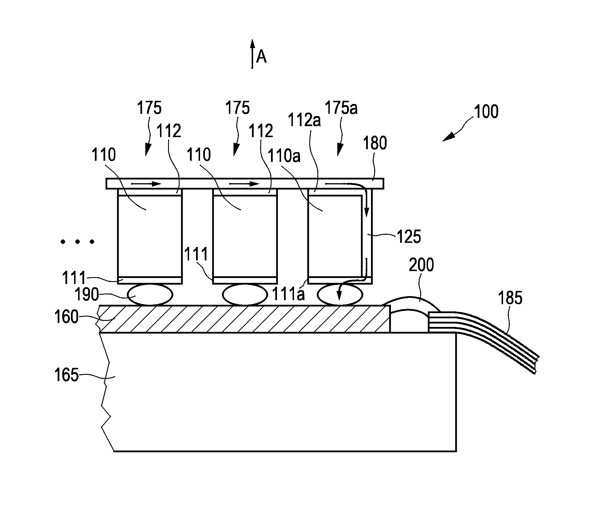
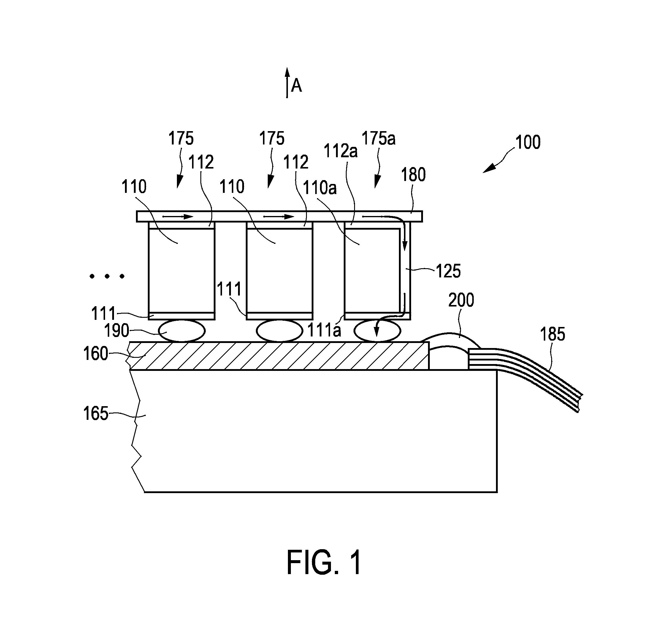
[0027]FIG. 1 shows a cross sectional view of an ultrasound transducer assembly 100 according to an embodiment. The ultrasound transducer assembly 100 comprises ultrasound transducer elements 175, 175a for transmitting ultrasound waves in a general transmission direction A. The ultrasound transducer elements 175, 175a can be arranged in a (one-dimensional) row or an (two-dimensional) array. For simplification purposes, in the cross sectional view of FIG. 1 only three of those ultrasound transducer elements are illustrated. It will be understood that there can be any number of additional ultrasound transducer elements arranged in the row or the array.

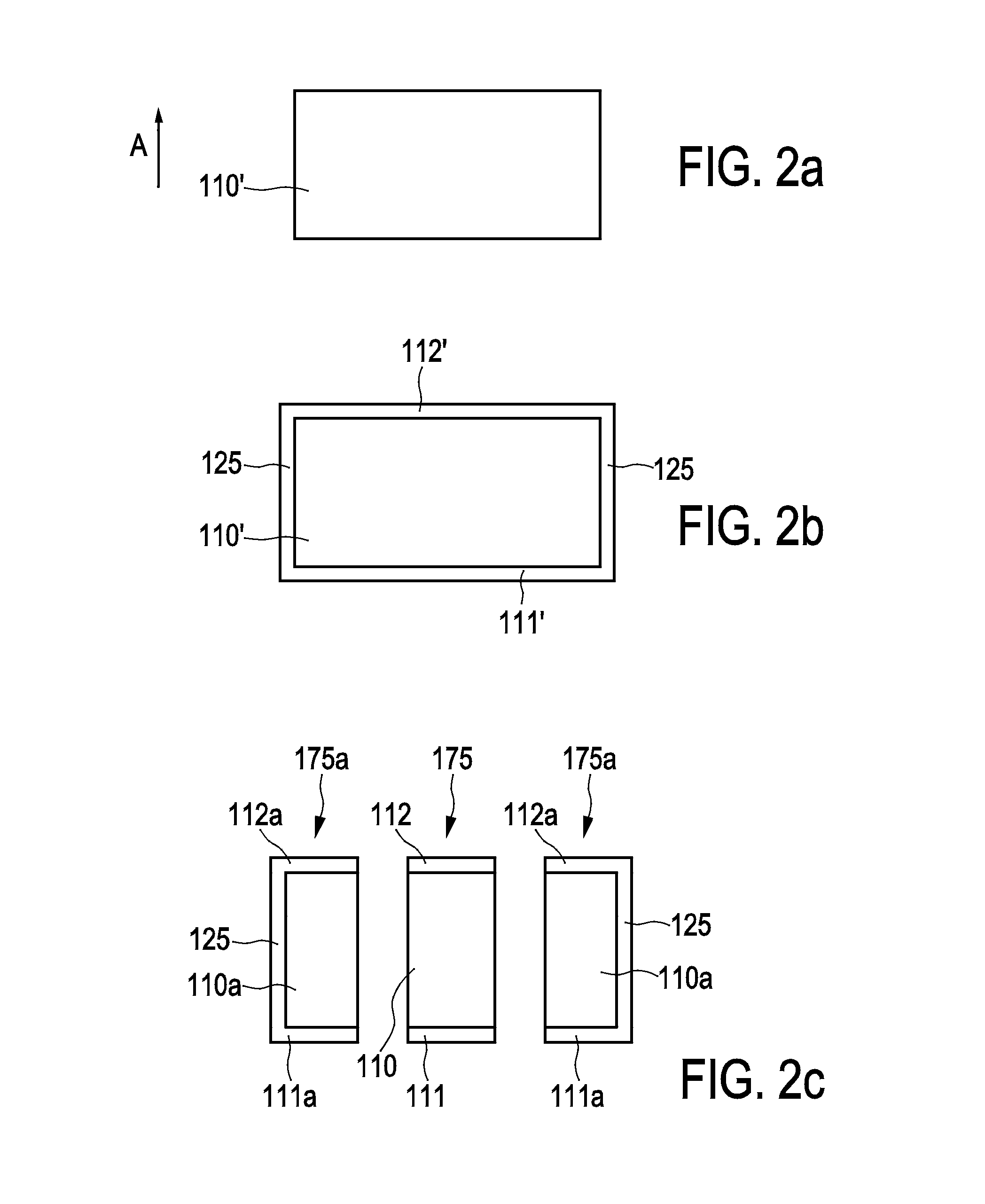
[0028]In the embodiment of FIG. 1, each of the ultrasound transducer elements 175, 175a comprises a piezoelectric layer 110, 110a having a top surface, a bottom surface and a side surface with respect to the general transmission direction A. The top surface and the bottom surface of the piezoelectric layer 110, 110a are each arranged perp...


PUM

PropertyMeasurementUnit
transmissionaaaaaaaaaa
conductiveaaaaaaaaaa
piezoelectricaaaaaaaaaa

Abstract

The present invention relates to an ultrasound transducer assembly (100) comprising ultrasound transducer elements (175, 175a) for transmitting ultrasound waves in a general transmission direction (A). Each of or each of part of the ultrasound transducer elements (175, 175a) comprises a piezoelectric layer (110, 110a) having a top surface, a bottom surface and a side surface with respect to the general transmission direction (A), as well as a bottom electrode layer (111, 111a) and a top electrode layer (112, 112a). A conductive layer (125) is applied at least partly on the side surface of at least one specific one (110a) of the piezoelectric layers, such that the conductive layer (125) is connected to the top electrode layer (112a) and the bottom electrode layer (111a) of said specific piezoelectric layer (110a).

Description

FIELD OF THE INVENTION[0001]The present invention relates to an ultrasound transducer assembly comprising ultrasound transducer elements for transmitting ultrasound waves in a general transmission direction. The present invention further relates to a method of manufacturing such ultrasound transducer assembly.BACKGROUND OF THE INVENTION[0002]US 2008 / 0315331 A1 discloses a transducer assembly having a ground connection routed through a via formed in a cMUT array and through an ASIC. A transducer module comprises a cMUT transducer subarray formed on a semiconductor substrate with a front electrode positioned over a membrane and with the membrane suspended over insulating supports. The individual cells include bottom electrodes for receiving signals from ASIC circuit cells. A conductive via is formed within the insulating support between adjacent transducer cells to connect the front electrode to a contact on the cMUT substrate. However, the transducer assembly disclosed in US 2008 / 031...

Claims


Application Information

Patent Timeline
Patent Type & Authority Applications(United States)
IPC IPC(8): H01L41/047H01L41/29B06B1/06
CPCH01L41/0475H01L41/29B06B1/0607B06B1/0622A61B8/4494Y10T29/42H10N30/875H10N30/06
Inventor SUDOL, WOJTEK
Owner KONINKLJIJKE PHILIPS NV
Why Eureka
Try Eureka