Optical-see-through head mounted display system and interactive operation

a display system and display technology, applied in the field of optical-see-through head mounted display system and interaction operating method, can solve the problems of erroneous shielding between real images, mutual interference, and use of see-through-type head mounted display in the augmented reality interaction system, and achieve the effect of convenient operation

Active Publication Date: 2014-05-22
IND TECH RES INST
View PDF4 Cites 22 Cited by
  • Summary
  • Abstract
  • Description
  • Claims
  • Application Information

AI Technical Summary

Benefits of technology

[0005]Accordingly, at least one objective of the present disclosure is to provide an optical-see-through head mounted display system and an interaction operating method capable of overcoming the issues of mutual interfering between the real image and the virtual image and the erroneous shielding between the real image and the virtual image and further capable of meeting the human operation patterns on operating the tablet personal computer so that the users can easily operates the tablet personal computer without having any learning or accommodation issue.

Problems solved by technology

The common issues of the see-through-type head mounted display comprises correction of the eye position, mutual interference between the real image and the virtual image and the erroneous shielding between the real image and the virtual image.
Hence, the use of the see-through-type head mounted display in the augmented reality interaction system confronts a lot of difficult and complicated issues.
Therefore, the see-through-type head mounted display is not as widely applicable as the immersion-type head mounted display.

Method used


Image

  • Optical-see-through head mounted display system and interactive operation
  • Optical-see-through head mounted display system and interactive operation
  • Optical-see-through head mounted display system and interactive operation

Examples


Embodiment Construction

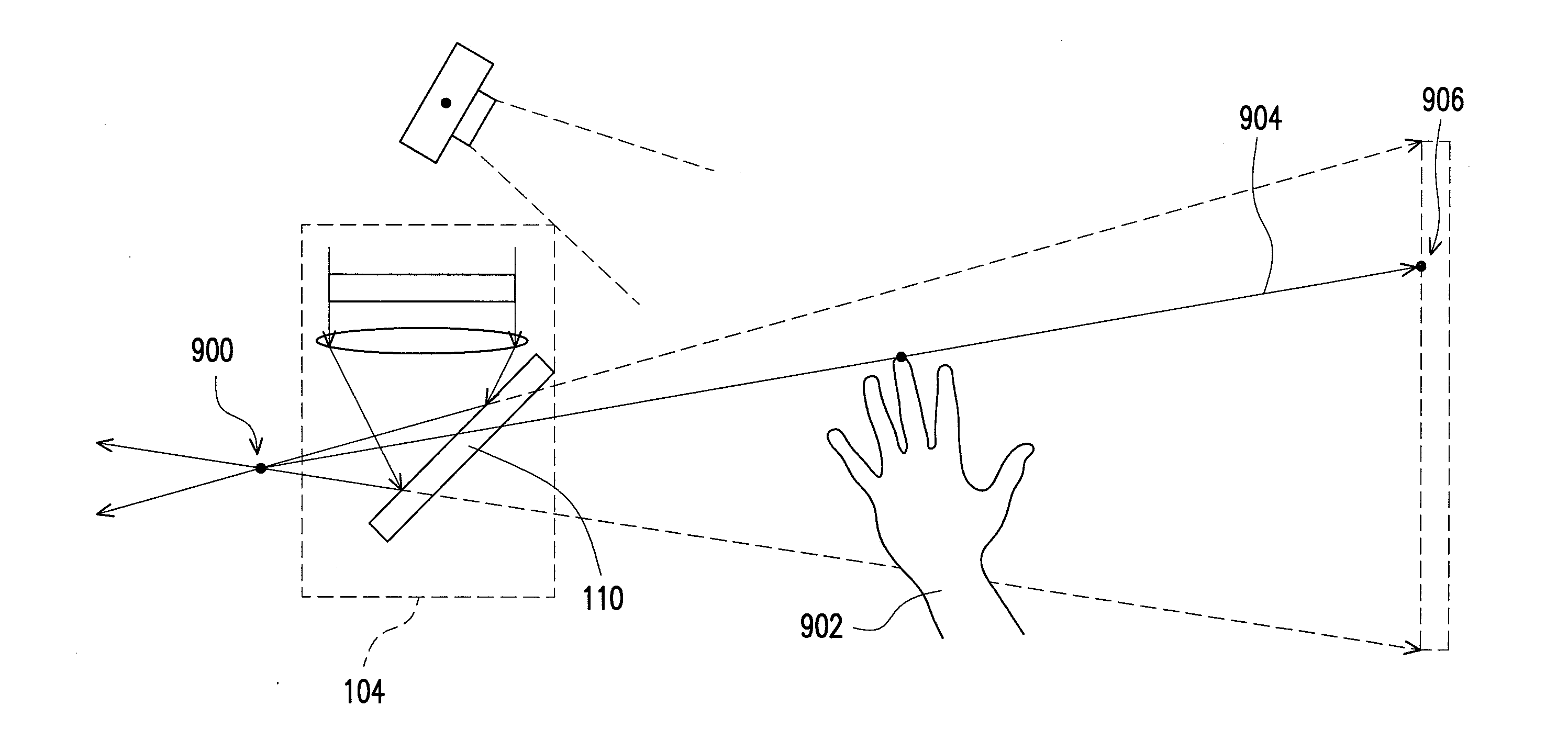
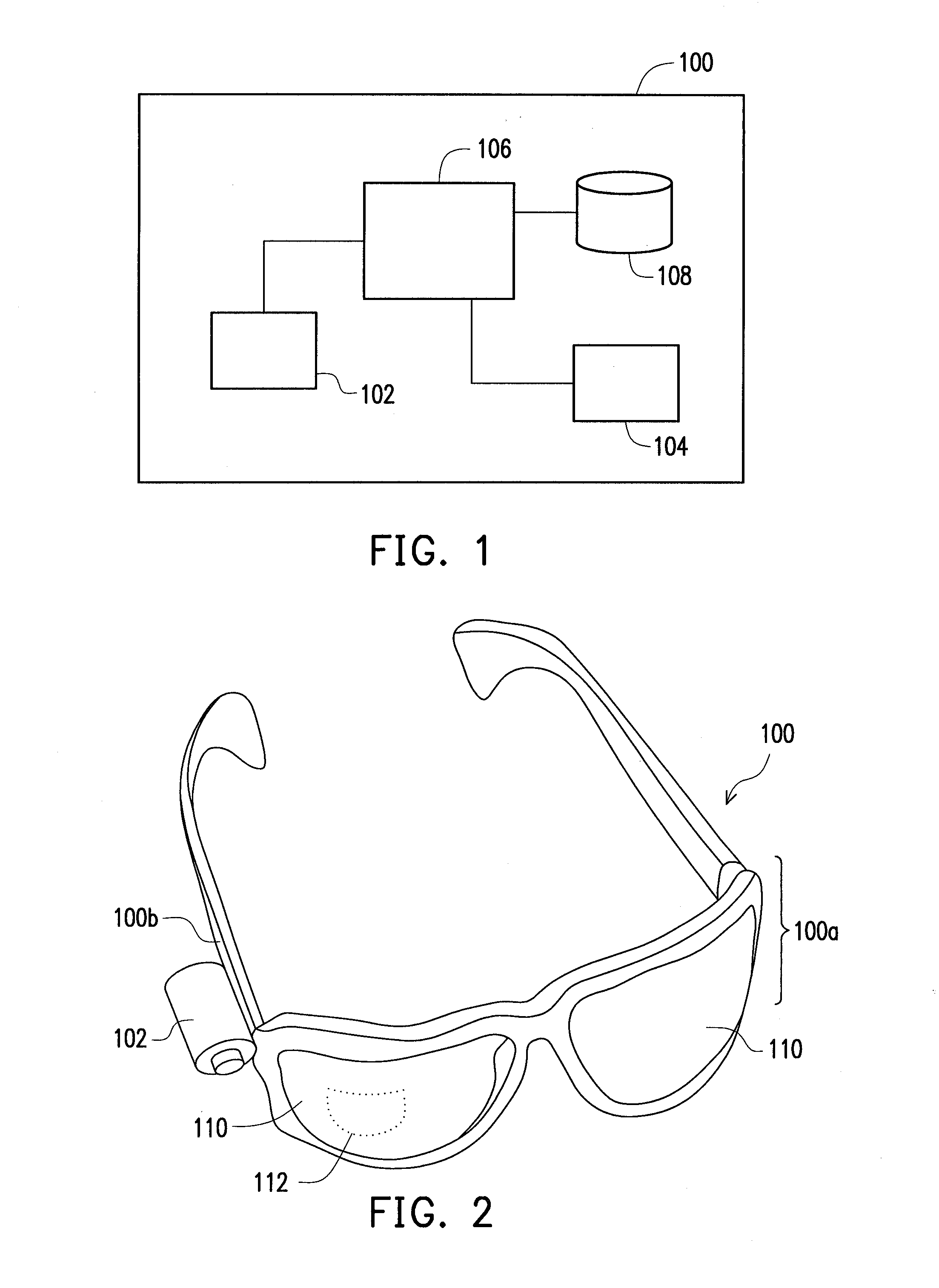
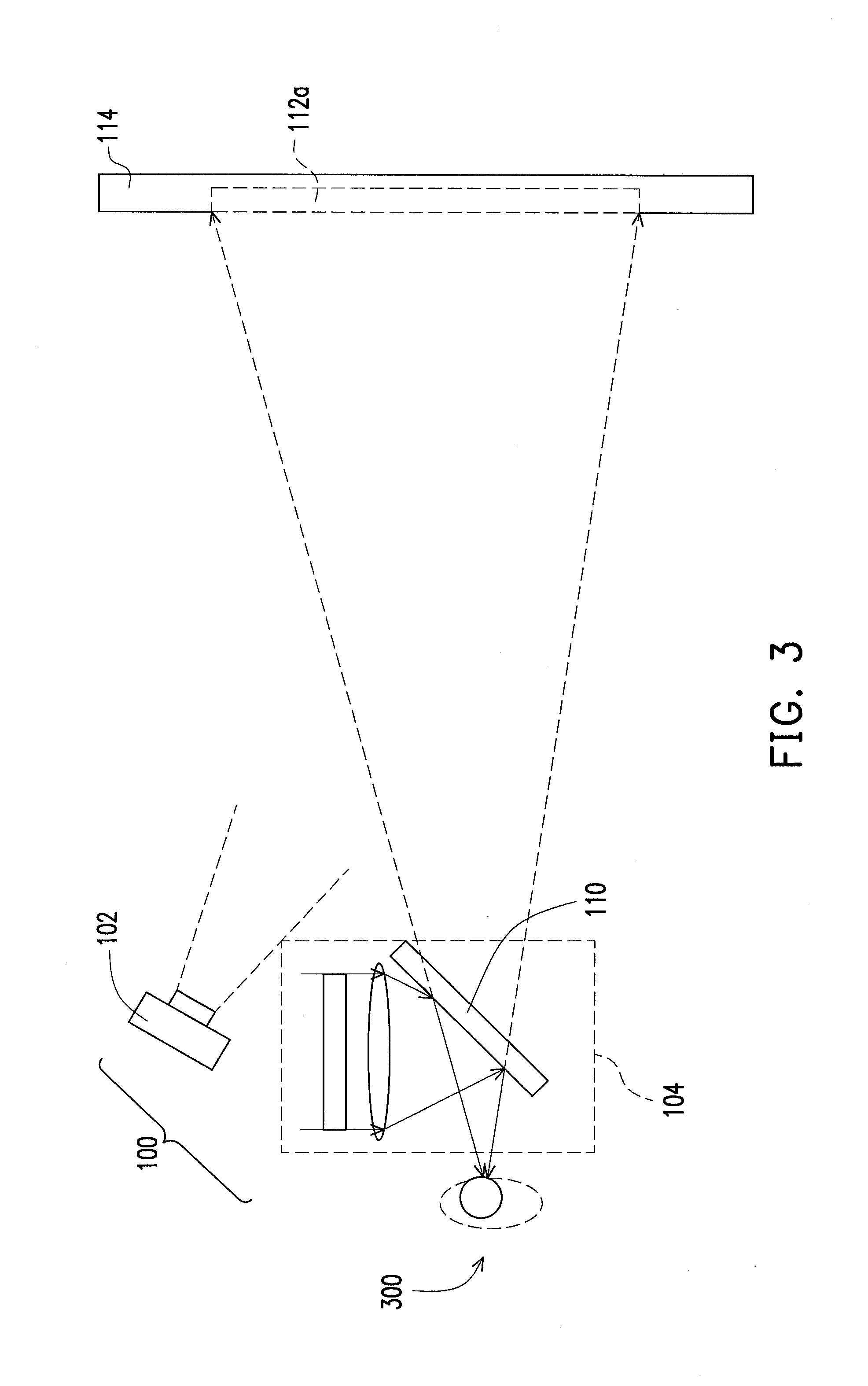
[0019]FIG. 1 is a schematic diagram showing an element structure of an optical-see-through head mounted display system according to one embodiment of the present disclosure. FIG. 2 is a schematic diagram showing a three-dimensional optical-see-through head mounted display system according to one embodiment of the present disclosure. FIG. 3 is a schematic diagram showing an optical-see-through head mounted display system according to one embodiment of the present disclosure. As shown in FIG. 1, FIG. 2 and FIG. 3, an optical-see-through head mounted display system 100 of the present embodiment is worn on a user (not shown) by an eyeglass-frame-type supporting holder 100a, for example. It should be noticed that the optical-see-through head mounted display system of the present disclosure is not limited to the eyeglass-frame-type supporting holder shown in FIG. 2. That is, the optical-see-through head mounted display system of the present disclosure can be worn on the user (user's head)...


PUM


Abstract

An optical-see-through head mounted display (HMD) system is provided. The optical-see-through HMD system has a camera for generating image frames, a display device and a processor. The processor proceeds an interactive operation on each image frame. In the interactive operation, an image analysis is performed on the image frame to obtain positioning information of a marker and 3-dimensional information of an input device. According to the positioning information, the 3-dimensional information and eye position of an user, an image shielding process is performed to correct a portion of the frame to be displayed which is corresponding to the input device and a collision test is performed according to the positioning information and the 3-dimensional information of an input device to determine whether the input device touches the virtual image displayed by HMD. Then, an event corresponding to the touch position of the virtual image is executed.

Description

CROSS-REFERENCE TO RELATED APPLICATION[0001]This application claims the priority benefit of Taiwan application serial no. 101143494, filed on Nov. 21, 2012. The entirety of the above-mentioned patent application is hereby incorporated by reference herein and made a part of this specification.FIELD OF DISCLOSURE[0002]The present disclosure relates to a head mounted display system and an operation method of the head mounted display system. More particularly, the present disclosure relates to an optical-see-through head mounted display system and an interaction operating method of the optical-see-through head mounted display system.BACKGROUND[0003]The wearable interaction device is one of the most prospective fields which the international companies are enthusiastically lay out the plan for after the development of the smart phone. The head mounted display (HMD) is one of the key devices in this field. The head mounted displays can be classified into immersion-type head mounted display...

Claims


Application Information

Patent Timeline
Patent Type & Authority Applications(United States)
IPC IPC(8): G06T19/00G02B27/01
CPCG02B27/017G02B2027/0138G02B2027/014G06F3/011
Inventor YU, CHIH-HSIANGTIAO, KUO-TUNGHUANG, WEI-JIACHEN, CHIA-CHENJENG, TZUAN-RENLIN, HSIEN-CHANG
Owner IND TECH RES INST
Why Eureka
Try Eureka