Method and apparatus of estimating wave velocity of negative pressure wave in a fluid transportation pipeline

Active Publication Date: 2014-05-22
IBM CORP
View PDF1 Cites 9 Cited by
  • Summary
  • Abstract
  • Description
  • Claims
  • Application Information

AI Technical Summary

Benefits of technology

The present invention provides methods and apparatus for estimating the wave velocity of negative pressure waves in fluid transportation pipelines. This is useful for identifying and locating wave sources, as well as estimating the velocity of the negative pressure wave in different sensor segments. This technology can help improve the monitoring and control of fluid transportation pipelines.

Problems solved by technology

However, the sound hammer simulation method is an offline simulation method, which cannot reflect the value of wave velocity when the leak actually occurs, because the wave velocity is subject to environmental factors such as a type of fluid (e.g., crude oil, diesel oil etc.), a fluid temperature, a leak location, topology of fluid transportation pipeline, and so on.
In addition, measurement process of the sound hammer simulation method needs extra cost.
However, it is actually not easy to acquire the accurate values of relevant parameters required by the empirical equation method, and the empirical equation itself possesses inaccuracy.

Method used


Image

  • Method and apparatus of estimating wave velocity of negative pressure wave in a fluid transportation pipeline
  • Method and apparatus of estimating wave velocity of negative pressure wave in a fluid transportation pipeline
  • Method and apparatus of estimating wave velocity of negative pressure wave in a fluid transportation pipeline

Examples


Embodiment Construction

[0024]Some preferable embodiments will be described in more detail with reference to the accompanying drawings, in which the preferable embodiments of the present disclosure have been illustrated. However, the present disclosure can be implemented in various manners, and thus should not be construed to be limited to the embodiments disclosed herein. On the contrary, those embodiments are provided for the thorough and complete understanding of the present disclosure, and completely conveying the scope of the present disclosure to those skilled in the art.

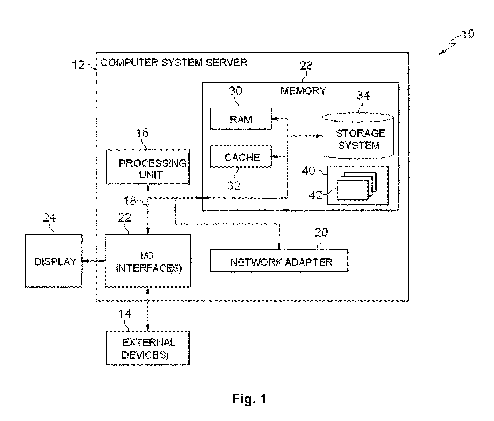
[0025]As will be appreciated by one skilled in the art, aspects of the present invention can be embodied as a system, method, or computer program product. Accordingly, aspects of the present invention can take the form of an entirely hardware embodiment, an entirely software embodiment (including firmware, resident software, micro-code, etc.) or an embodiment combining software and hardware aspects that can all generally be referred ...


PUM


Abstract

A method and apparatus for estimating a wave velocity of negative pressure wave in a fluid transportation pipeline. The method including: receiving a plurality of pressure signals from a plurality of sensors; determining time differences produced by the negative pressure wave reaching the adjacent sensors based on the received pressure signals; determining a wave source sensor segment where a wave source of the negative pressure wave is located; and estimating the wave velocities of the negative pressure wave in a non-wave source sensor segment and the wave source sensor segment.

Description

CROSS-REFERENCE TO RELATED APPLICATION[0001]This application claims priority under 35 U.S.C. §119 from Chinese Patent Application No. 201210465977.1 filed Nov. 16, 2012, the entire contents of which are incorporated herein by reference.FIELD OF THE INVENTION[0002]The present invention relates to leak detection and locating in a fluid transportation pipeline, and more particularly, to a method and apparatus for estimating a wave velocity of negative pressure wave in a fluid transportation pipeline.DESCRIPTION OF THE RELATED ART[0003]Leak detection and locating is an important method in fluid transportation pipeline management. The existing methods for pipeline leak detection and locating include acoustic pressure wave (negative pressure wave) detection and locating method, balancing method, statistical method, real time transient model (RTTM) method etc., wherein the acoustic pressure wave detection and locating method is the most commonly used method due to its low cost, high leak d...

Claims


Application Information

Patent Timeline
IPC IPC(8): G01F9/00
CPCG01M3/2815
Inventor DUAN, NINGHUANG, JINLEE, JUHNYOUNGTIAN, CHUNHUAYAN, JUNCHIWANG, YU
Owner IBM CORP
Why Eureka
Try Eureka