
Multi-parameter fiber bragg grating sensing pipe health monitoring system

A health monitoring system, optical fiber grating technology, applied in pipeline systems, measuring devices, instruments, etc., can solve problems such as errors, inability to prevent in advance, leakage, etc., and achieve improved accuracy, good acoustic transmission, and high measurement accuracy Effect

Inactive Publication Date: 2017-07-18
WUHAN UNIV OF TECH
View PDF8 Cites 12 Cited by
  • Summary
  • Abstract
  • Description
  • Claims
  • Application Information

AI Technical Summary

Problems solved by technology

[0003] The current pipeline health monitoring is often limited to monitoring whether there is leakage, and does not pay much attention to the monitoring of the rest of the health status. However, the leakage of the pipeline is the result of gradual damage from quantitative change to qualitative change. Only monitoring whether there is leakage cannot prevent it in advance Moreover, the current judgment of leakage is based on the appearance of negative pressure waves, but during pipeline transportation, changes in transmission conditions (such as starting and stopping pumps, adjusting flow valves, etc.) will also affect the parameters of the pipeline head and end Balanced state, thus causing the appearance of negative pressure waves, since it is impossible to distinguish whether the appearance of negative pressure waves is caused by pipeline leakage or normal operation, therefore, judging whether a leak occurs based only on the appearance of negative pressure waves will cause a large error

Method used


Image

  • Multi-parameter fiber bragg grating sensing pipe health monitoring system
  • Multi-parameter fiber bragg grating sensing pipe health monitoring system

Examples


Embodiment Construction

[0021] The present invention will be further described below in conjunction with the accompanying drawings and embodiments.

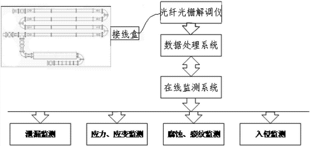
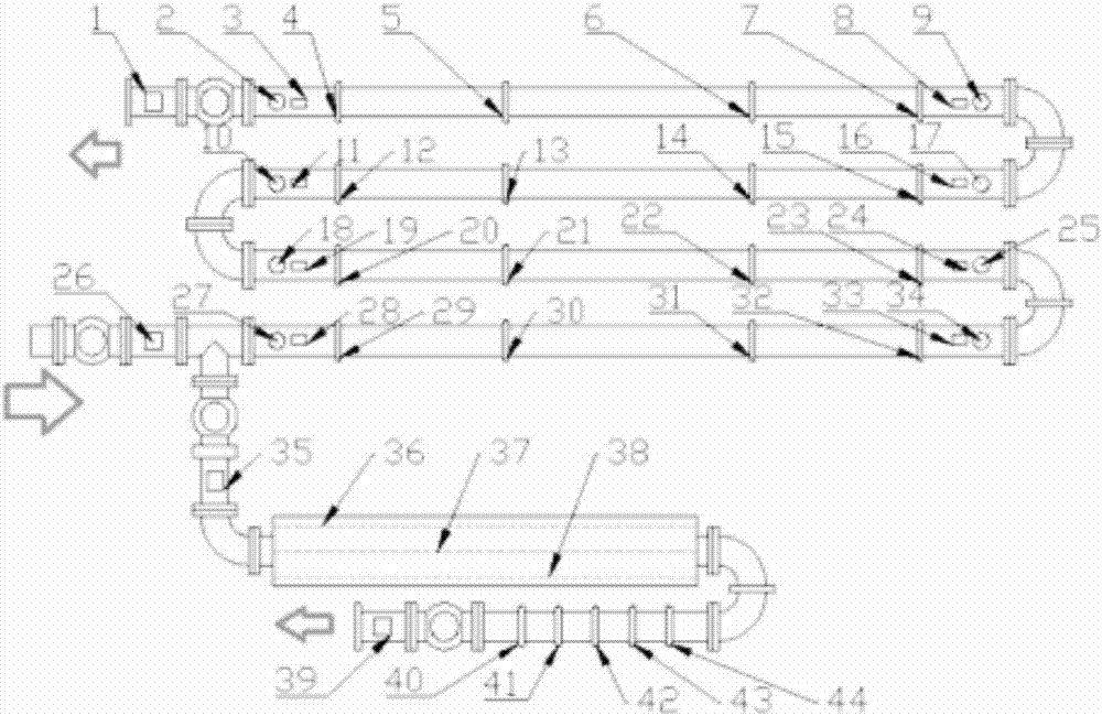
[0022] Such as figure 1 As shown, a multi-parameter fiber grating sensing pipeline health monitoring system is used to monitor multiple parameters of the pipeline and evaluate the health status of the pipeline through the collected parameters, including fiber grating sensors distributed on the pipeline and connected with The fiber grating sensor is connected in turn to the junction box, grating fiber demodulator, data processing system and on-line monitoring system, such as figure 2 As shown, fiber grating flow sensors are installed inside the key nodes of the main line and branch lines of the pipeline, and fiber grating pressure sensors are installed inside the pipeline near the valves and elbows. It is judged by the changes of the monitored flow and pressure and the distribution of the flow. There is leakage; for unburied pipelines, install fiber op...


PUM


Abstract

The invention relates to a multi-parameter fiber grating sensing pipeline health monitoring system, which includes a fiber grating sensor, a junction box, a grating fiber optic demodulator, a data processing system and an online monitoring system, and optical fibers are installed at key nodes of pipeline main lines and branch lines Grating flow sensor, fiber grating pressure sensor installed near the valve and elbow of the pipeline, for the unburied pipeline, install the fiber grating acoustic emission sensor on the outer wall of the pipeline near the valve and elbow, and install the fiber grating acoustic emission sensor on the outer wall of the pipeline in the axial direction Fiber Bragg grating strain sensors arranged around the circumference are installed at intervals to monitor the stress distribution of the outer wall of the pipeline when there is no leakage and the strain on the outer wall of the pipeline caused by negative pressure waves when there is leakage. For buried pipelines, fiber gratings are arranged around the pipeline to measure temperature For optical cables, fiber grating anti-intrusion optical cables are laid above the pipeline. The system can monitor various parameters and judge various health states of the pipeline, and the accuracy of leakage judgment is high.

Description

technical field [0001] The invention belongs to the field of pipeline monitoring, in particular to a multi-parameter optical fiber grating sensing pipeline health monitoring system. Background technique [0002] Pipelines are widely used in the transportation of oil, gas, water, etc. and the laying of power cables. The health status of pipelines determines the service life and failure rate of pipelines. In order to reduce the failure rate, it is necessary to monitor the health of pipelines. [0003] The current pipeline health monitoring is often limited to monitoring whether there is leakage, and does not pay much attention to the monitoring of the rest of the health status. However, the leakage of the pipeline is the result of gradual damage from quantitative change to qualitative change. Only monitoring whether there is leakage cannot prevent it in advance Moreover, the current judgment of leakage is based on the appearance of negative pressure waves, but during pipeline ...

Claims


Application Information

Patent Timeline
Patent Type & Authority Applications(China)
IPC IPC(8): F17D5/02G01D21/02
CPCF17D5/02G01D21/02
Inventor 梁磊许儒泉冯坤徐刚王慧张健吴慧峰李东旭曹珊仇磊涂彬段细云蔡彦璞王仁亮罗玉文王永皎
Owner WUHAN UNIV OF TECH
Learn More