
Blast compression wave absorbing device

a compression wave and wave absorbing technology, applied in the field of blast effects suppression devices, can solve the problems and achieve the effect of reducing peak pressure and duration

Inactive Publication Date: 2006-02-09
PONOMAREV VLADIMIR +1
View PDF1 Cites 10 Cited by
  • Summary
  • Abstract
  • Description
  • Claims
  • Application Information

AI Technical Summary

Benefits of technology

[0015] (a) to provide a blast compression wave absorbing device which allows reduction of peak overpressure without transfer of impulse to supporting structure;
[0016] (b) to provide a blast compression wave absorbing device able to reduce the impulse transferred to the structure to be protected being attached to the same structure;
[0017] (c) to provide a blast compression wave absorbing device which can protect the large areas of building from distance;
[0019] (e) to provide a blast compression wave absorbing device with ability to reduce the overpressure and associated stress in containment structures where venting is not sufficient.
[0021] The present invention provides a blast compression wave absorbing device, comprising means for generation of a negative pressure wave in predetermined area near the object to be protected. After explosion, the negative pressure wave interferes with a blast compression wave and reduces its peak pressure and duration.

Problems solved by technology

After explosion, the negative pressure wave interferes with a blast compression wave and reduces its peak pressure and duration.

Method used


Image

  • Blast compression wave absorbing device
  • Blast compression wave absorbing device
  • Blast compression wave absorbing device

Examples


Embodiment Construction

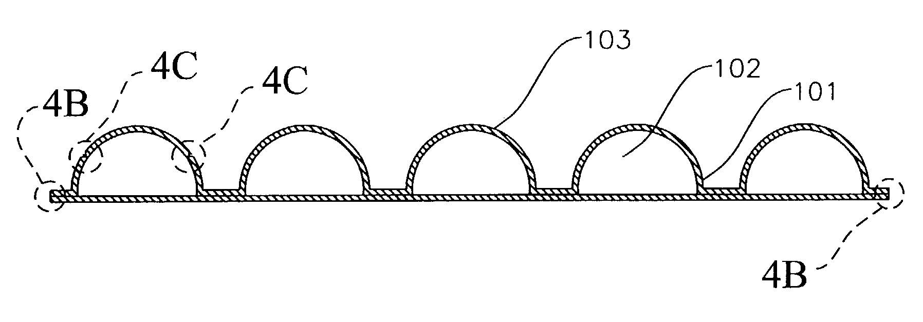
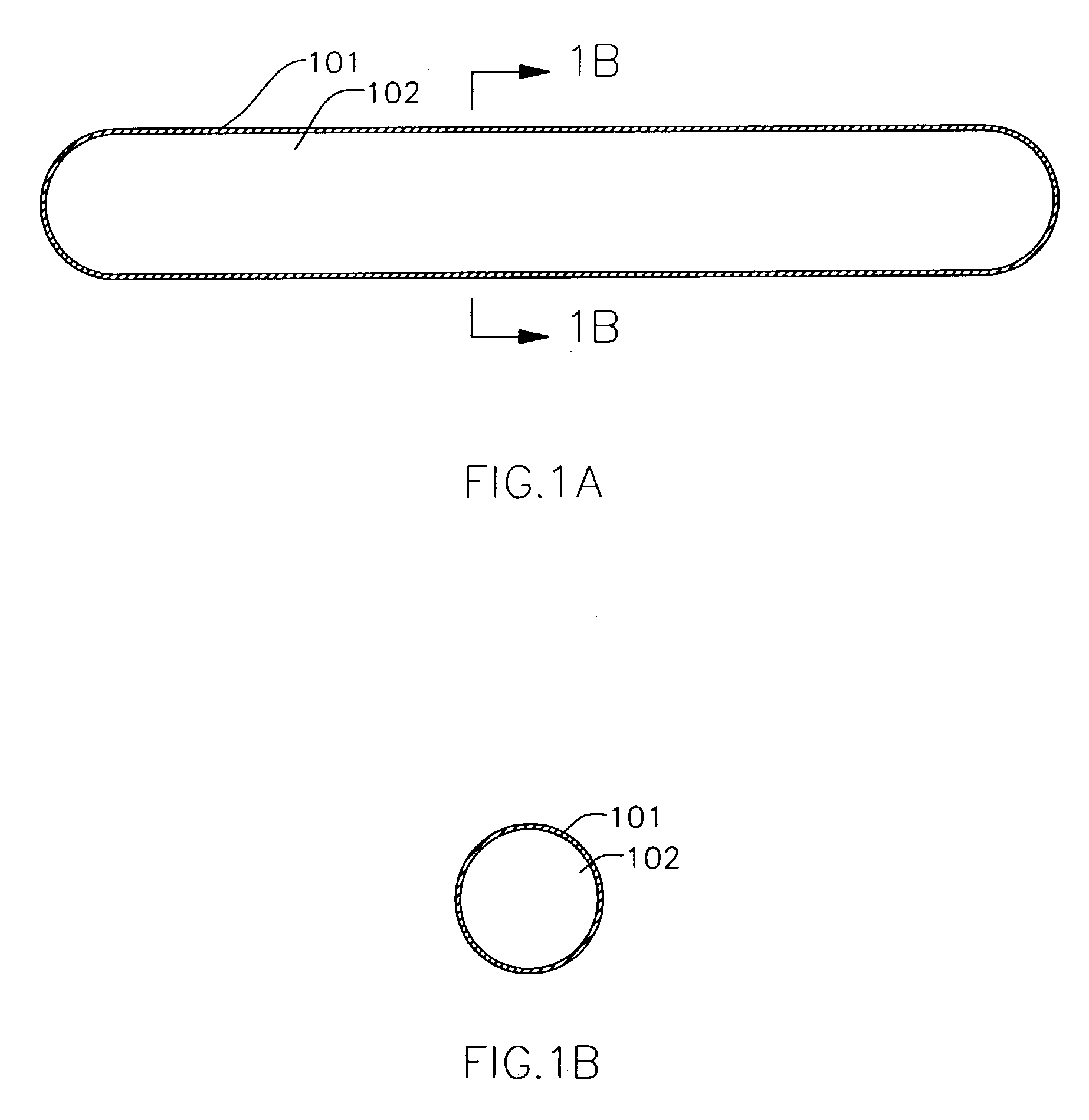
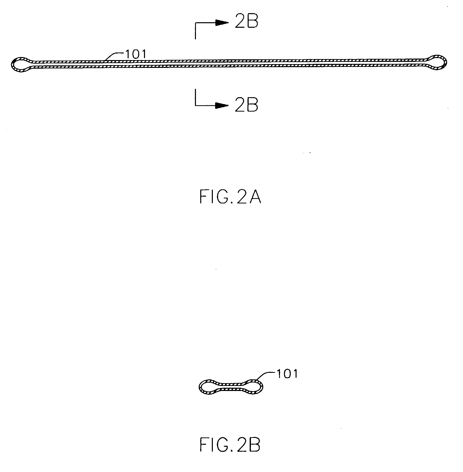
[0042] Referring to FIG. 1A and FIG. 1B of the drawings, a blast compression wave absorbing device consists of a hollow thin-walled cylindrical container 101 having an interior 102 filled with a gas (for example, with air, nitrogen or carbon dioxide). The gas has a pressure below ambient pressure (below atmospheric pressure or, for submerged objects, below hydrostatic pressure at the depth of installation), for example, 1 psia (7 kPa abs). The container 101 has sufficiently thin walls designed to collapse or rupture at a predetermined external pressure, for example, at 4 psig (27.2 kPa gauge). The container 101 in collapsed form can be seen in FIG. 2A and FIG. 2B. If the container 101 collapses, the ambient air (or water) starts to fill the void (the space previously being a part of container). This movement of air (or water) generates an area with reduced pressure around the container (a negative pressure wave). The negative pressure wave interferes with blast compression wave and ...


PUM


Abstract

A blast compression wave absorbing device comprises a container filled with gas or air under pressure below ambient pressure (under vacuum). The device is positioned close to the facility or structure being protected, in atmosphere or under water. When a blast compression wave reaches the device, in accordance with various embodiments of the invention, the container collapses, ruptures, or its interior is being connected to the environment through rupturable diaphragm or fast-actuating valve. The ambient air starts to fill the internals of the container generating a negative pressure wave, which interferes with blast compression wave and produces a resulting pressure wave with reduced pressure and impulse affecting the facility or structure to be protected. The device can be used in a counter-terrorism operations, to protect high-risk facilities (nuclear and military installations, petrochemical plants, embassies), submerged structures, or to protect personnel in tunnels and bunkers from shock waves of fuel-air explosives.

Description

CROSS-REFERENCE TO RELATED APPLICATIONS [0001] Not applicableBACKGROUND OF THE INVENTION—FIELD OF INVENTION [0002] The present invention relates to blast effects suppression devices used to limit the damage associated with explosions, specifically, to reduction of impulse and overpressure of compression waves in order to minimize the damages in area being protected. BACKGROUND OF THE INVENTION [0003] Terrorist bombings have always been a problem. In many instances, the bomb or explosive device is placed close to public buildings, embassies, sensitive (nuclear) installations, often in a parked vehicle. The damage associated with explosion is related to air compression waves (also known as pressure waves or shock waves). The duration of this overpressure may be milliseconds or more, and significant impulse associated with compression wave results in damages to structures (buildings) especially to buildings having large surface areas. [0004] Various means can be used to reduce compress...

Claims


Application Information

Patent Timeline
Patent Type & Authority Applications(United States)
IPC IPC(8): B64F1/26
CPCB64D37/32F42D5/045B64D2037/325
Inventor PONOMAREV, VLADIMIRPONOMARYOVA, IRYNA
Owner PONOMAREV VLADIMIR
Learn More