
Method and a device for deformation of a material body

a material body and deformation technology, applied in the direction of forging hammers, presses, manufacturing tools, etc., can solve the problems of unwanted structures and phases, high probability, and martensite in steel

Inactive Publication Date: 2006-04-18
HYDROPULSOR
View PDF12 Cites 3 Cited by
  • Summary
  • Abstract
  • Description
  • Claims
  • Application Information

AI Technical Summary

Benefits of technology

[0008]The inventor has discovered that a lower total energy needs to be supplied to the material body and that a comparatively low temperature increase in the material body can be achieved while still achieving the desired deformation of the material body by means of the method according to the invention.
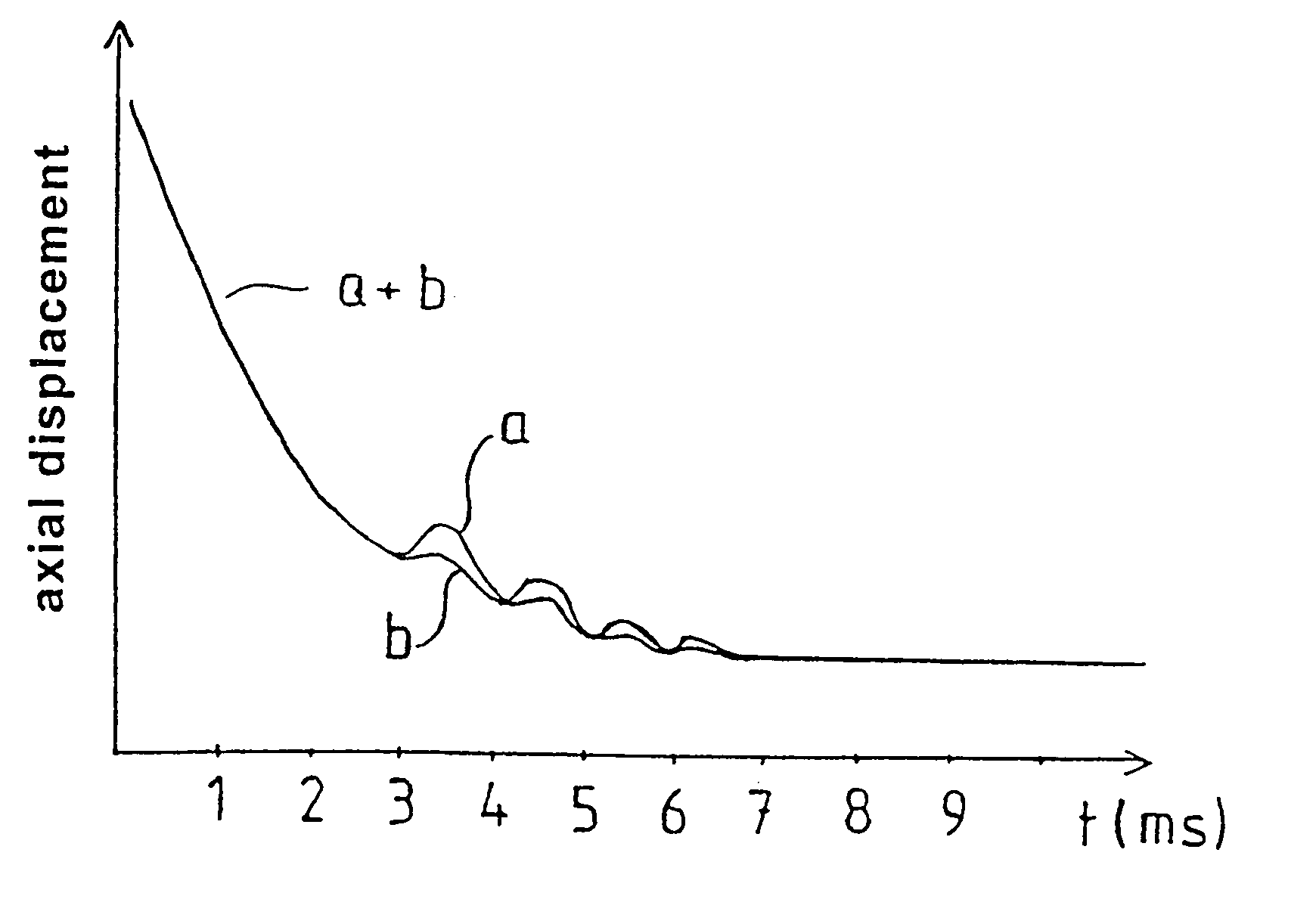
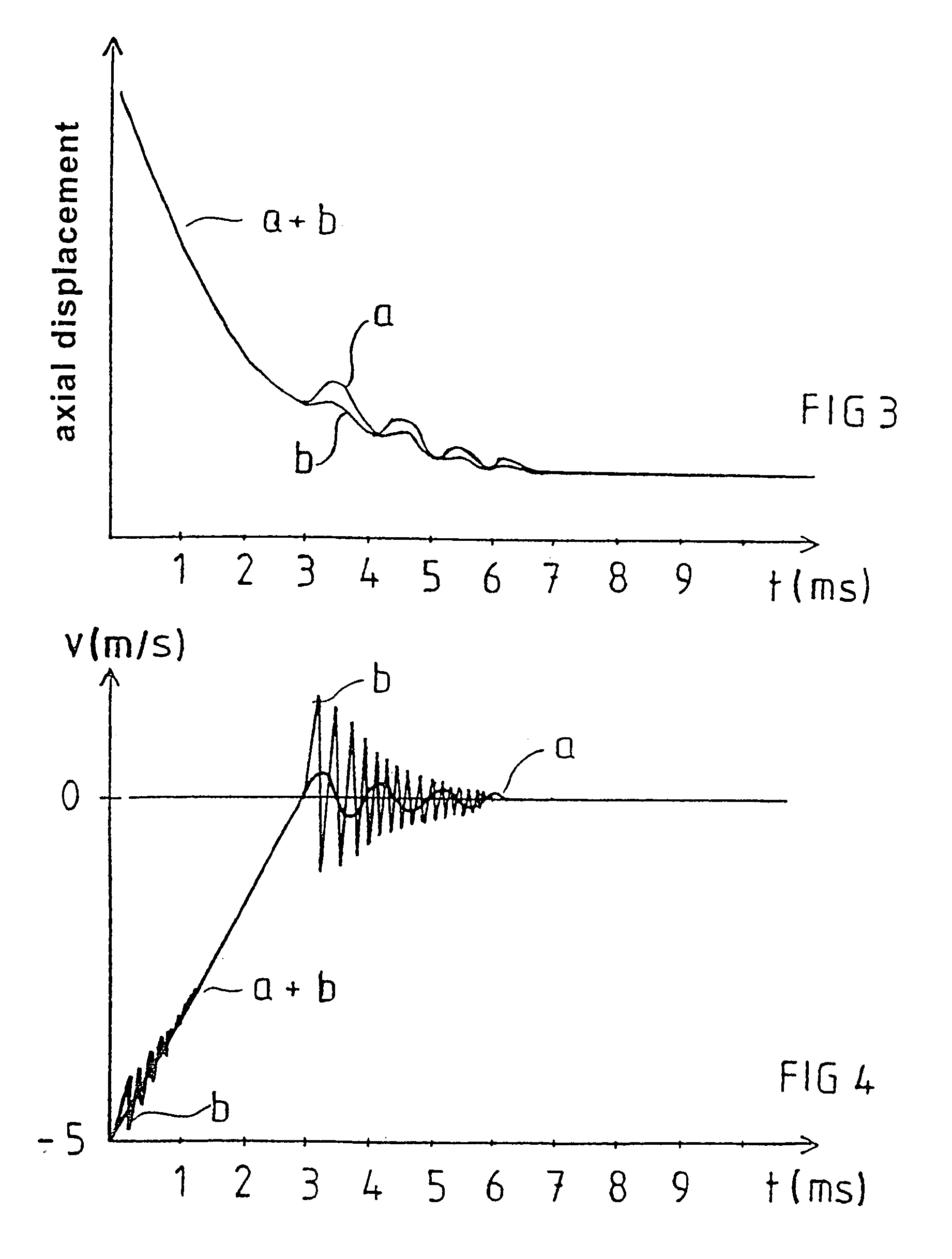
[0011]According to a further preferred embodiment the impulse, with which the stamping member hits the material body, decreases with each impact within said series. When a stroke only comprising two impacts, a first and a second one, is applied against the material body, the first impact has a larger impulse than the second. Thanks to the effect of the wave on the material body, such a large impulse from the second impact is no longer necessary to generate a certain desired additional plastic deformation. Also in practice it becomes easier to achieve a second impact with a smaller impulse than the first impact within such a short period of time here referred to (approximately 1 ms), for instance by effective damping of the rebound motion. The possibility to apply a second impact with a larger impulse than the first or previous impact shall however not be excluded, if required.
[0013]According to a further preferred embodiment the material body comprises a powder, provided in a mould. The deformation of the powder body comprises a compacting thereof. The method according to the invention offers a fast and effective way of compacting powder, for instance cemented carbide powder, without any unnecessarily high temperatures, which could lead to forming of undesired structures and / or phases being generated in the powder. As mentioned above, the prior art suggests that the powder material body is compacted in three steps, a first step when a light stroke is applied against the body in order to achieve an initial orientation of the powder particles, a second step when a very powerful stroke is directed against the powder to achieve local adiabatic coalescence of the powder particles so that these are pressed together to high density, and a third step, at which a stroke of medium high energy is applied against the powder body and a final forming takes place. The method according to the invention could with advantage be applied at the second step and / or possibly at the third step.
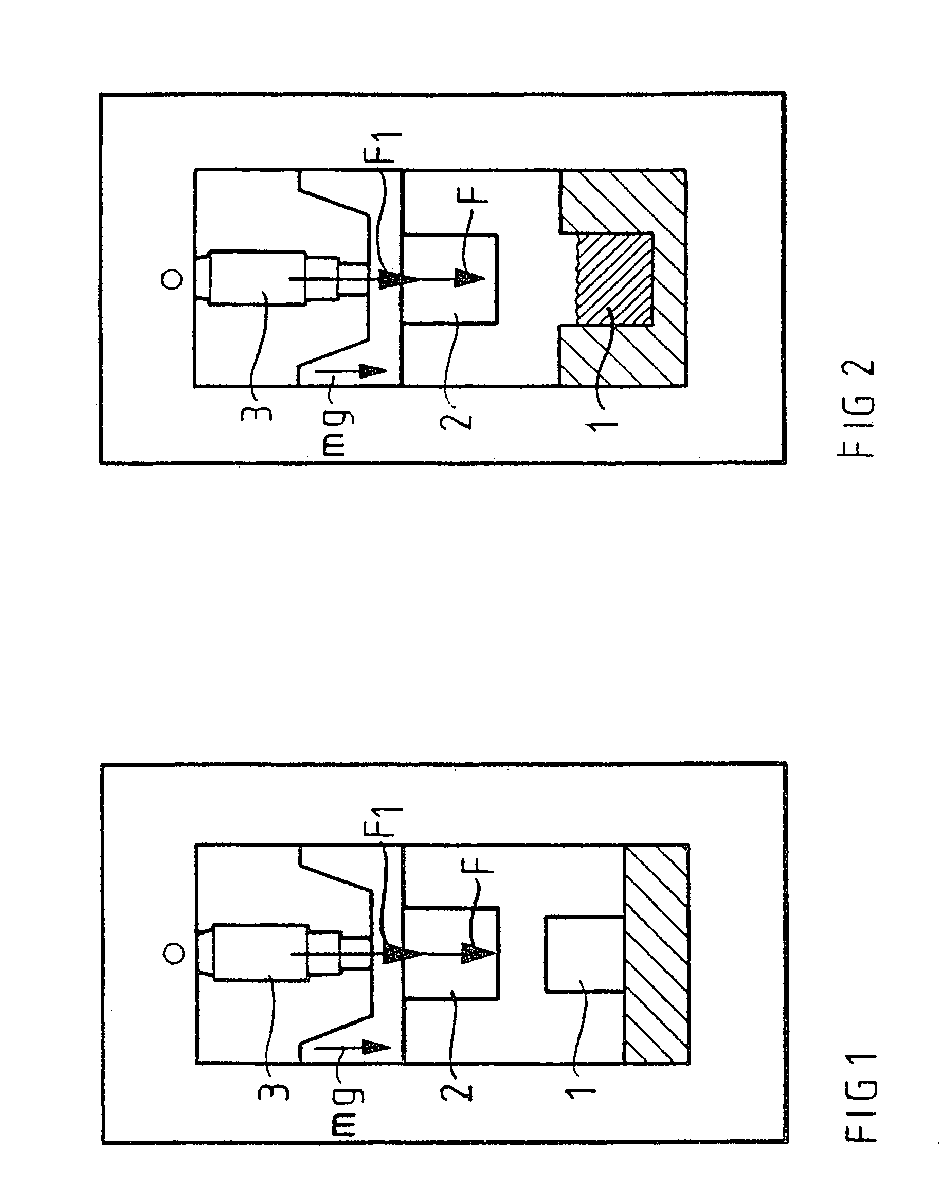
[0017]According to a further preferred embodiment, the device comprises means for application of a force F1 to the stamping member, which force acts in the direction towards the material body and counteracts the rebound. By a suitable choice of the mass of the stamping member, the drop and the size of the force F1 applied it is consequently possible to control the time between two consecutive impacts of the stamping member against the material body. The applied force F1 not only counteracts the rebound but also contributes to actively pushing the stamping member in the direction towards the material body.
[0018]According to a further preferred embodiment, the device is arranged to perform a series of impacts by means of the stamping member against the material body within said period. Every single impact thereby takes place with such a velocity of the stamping member that a following rebound of it is generated. The device can thereby comprise means for controlling the size of the force applied on the stamping member, for instance so that it gradually subsides with every additional rebound in order to achieve a harmonic and not too fast a damping of the motions of the stamping member against the material body.

Problems solved by technology

The probability is high that unwanted structures and phases, for instance martensite in steel, are obtained as a result of this process.

Method used


Image

  • Method and a device for deformation of a material body
  • Method and a device for deformation of a material body
  • Method and a device for deformation of a material body

Examples


Embodiment Construction

[0029]In FIGS. 1 and 2 a device for deformation of a material body 1 is shown schematically. The device comprises a stamping member 2, arranged to be conveyed towards and hit the material body 1 with such a velocity that a rebound motion of the stamping member 2 is generated. Thereby the material body 1 is deformed.

[0030]The material body in FIG. 1 is formed by a material in solid form, preferably a solid metal. In FIG. 2 the material body 1 is formed by a powder preferably already being lightly compacted, either by means of a light stroke of the stamping member or some other similar member. The device is arranged to achieve an immediate and relatively large deformation of the material body 1 by means of a powerful stroke of the stamping member.

[0031]The stamping member 2 is so provided that it under influence of the gravity force acting on it is accelerated towards the material body 1. The mass m of the stamping member 2 is preferably substantially larger than the mass of the mater...


PUM

PropertyMeasurementUnit
of timeaaaaaaaaaa
heightaaaaaaaaaa
massaaaaaaaaaa

Abstract

The device comprises a stamping member (2) arranged to be conveyed towards and hit a material body (1) with such a velocity that a rebound motion of the stamping member (2) is generated while a permanent deformation of the material body (1) is generated. The device has structure (3) for counteracting the rebound and generating at least one additional impact of the stamping member (2) against the material body (1) within a period, during which kinetic energy in the material body (1) generates an additional deformation in the body.

Description

BACKGROUND OF THE INVENTION AND PRIOR ART[0001]The present invention is related to a method for deformation of a material body, in which a stamping member with a mass m is conveyed towards and hits a material body with such a velocity that at least one rebound motion of the stamping member is generated, while a permanent deformation of the body is generated. The invention also relates to a device for deformation of a material body, comprising a stamping member arranged to be conveyed towards and hit a material body with such a velocity that a rebound motion of the stamping member is generated, while a permanent deformation of the material body is generated.[0002]Through the earlier patent application No. WO 97 / 00751 of the applicant it is known to fix a material body, either in solid form or in form of a powder of grain, pellets or similar and with one single or several consecutive strokes by means of a striking unit achieve adiabatic coalescence in the material body, through which ...

Claims


Application Information

Patent Timeline
Patent Type & Authority Patents(United States)
IPC IPC(8): B21J5/00B21J7/00B21J9/10B22F3/02B22F3/17B30B5/00
CPCB21J5/00B21J9/10B22F3/17B22F2998/00B22F3/087
Inventor TROIVE, LARSBERGSTROM, YNGVE
Owner HYDROPULSOR
Learn More