Starting device for at least one combustion engine, in particular cable pull starting device

a technology of starting device and combustion engine, which is applied in the direction of engine starting device, machine/engine, muscle operated starter, etc., to achieve the effect of long li

Active Publication Date: 2012-09-20
MAKITA CORP
View PDF15 Cites 1 Cited by
  • Summary
  • Abstract
  • Description
  • Claims
  • Application Information

AI Technical Summary

Benefits of technology

[0009]The object of the present invention now is to provide a starting device which has a long lifespan even when used for different engine sizes.
[0013]With such a configuration of the coupling link, which acts as damping spring, the force paths can be significantly shortened. Thus, the components cable drum and / or cable sheave and / or driver can be designed in a material-saving manner.
[0015]With such a configuration of the invention it is now possible that force peaks, which develop when the driver springs back or upon overloading during the starting operation and act on the rotary stop and the surrounding plastic components such as cable drum, cable sheave and driver, are lessened. The components thus have a longer lifespan and can be designed lighter. In addition to this, the operating comfort for the user is also increased.
[0016]In that a damping element is now integrated on the rotary stop a possible striking and thus for example the impulse of the driver on the rotary stop when turning back and / or during the overload stop can be lessened, which results in an extension of the component lifespan and an increase of the operating comfort.

Problems solved by technology

The operation of a starting device for a combustion engine, in particular a cable pull starting device for a combustion engine, in particular for a two-stroke or four-stroke engine, frequently posed problems in the past because periodically high reaction forces occur during starting through the compression in the combustion engine, as a result of which changing and temporarily very high forces are acting on the hand of the operating person.

Method used


Image

  • Starting device for at least one combustion engine, in particular cable pull starting device
  • Starting device for at least one combustion engine, in particular cable pull starting device
  • Starting device for at least one combustion engine, in particular cable pull starting device

Examples


Embodiment Construction

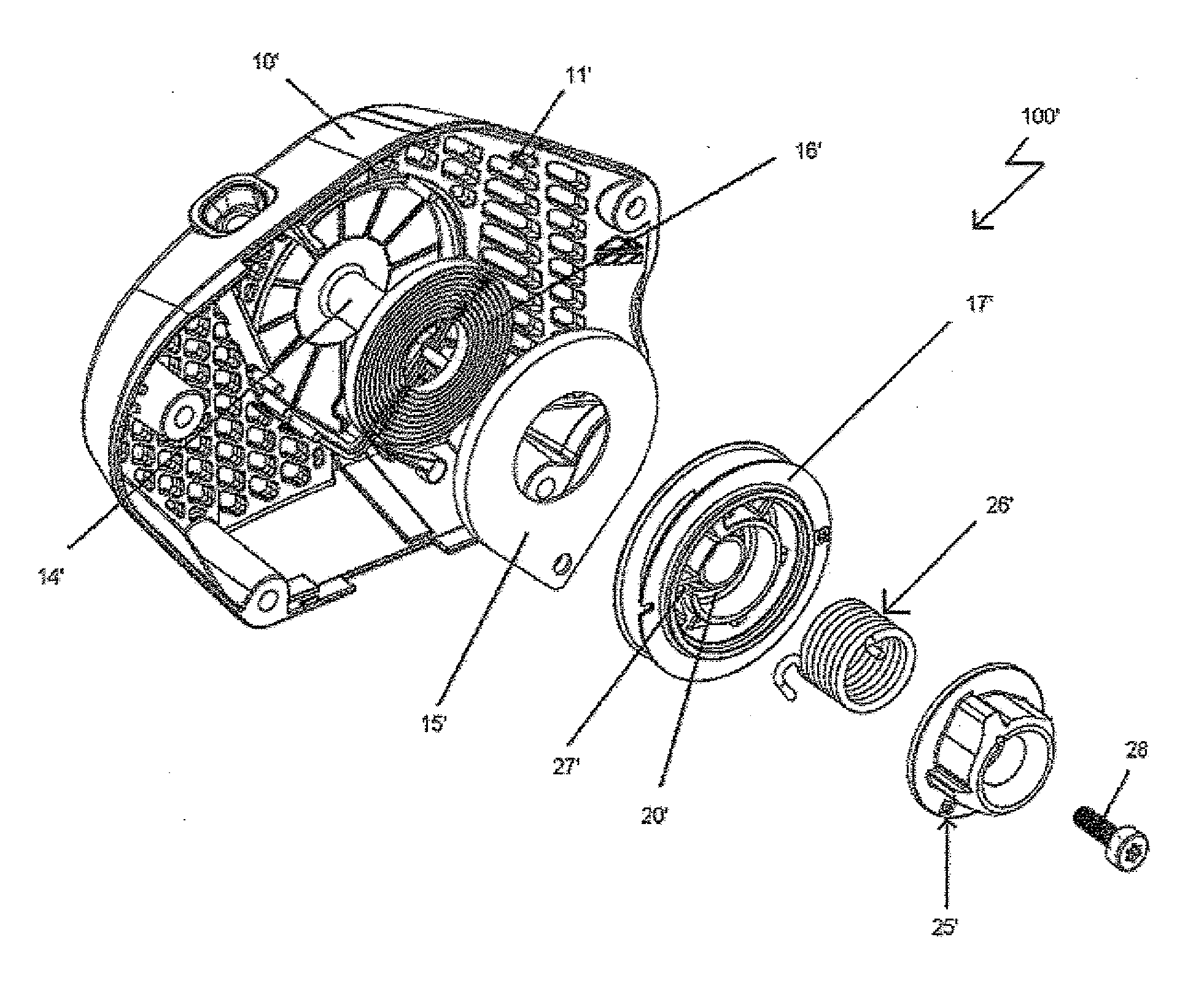
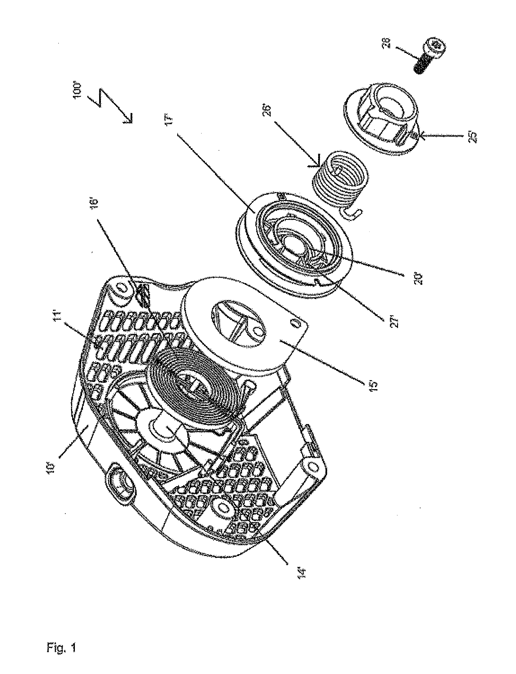
[0025]FIG. 1 shows a starting device 100, as it is also already known from the prior art. Such a starting device 100 is intended for the manual starting of a combustion engine, which for example can belong to a power chainsaw. The cable pull starting device 100 is accommodated in a housing 10, which constitutes a removable lid of the engine housing provided with ventilation slits 11, in which among other things an air cowling 12 and a pole wheel 13 adjoining thereto is integrated.

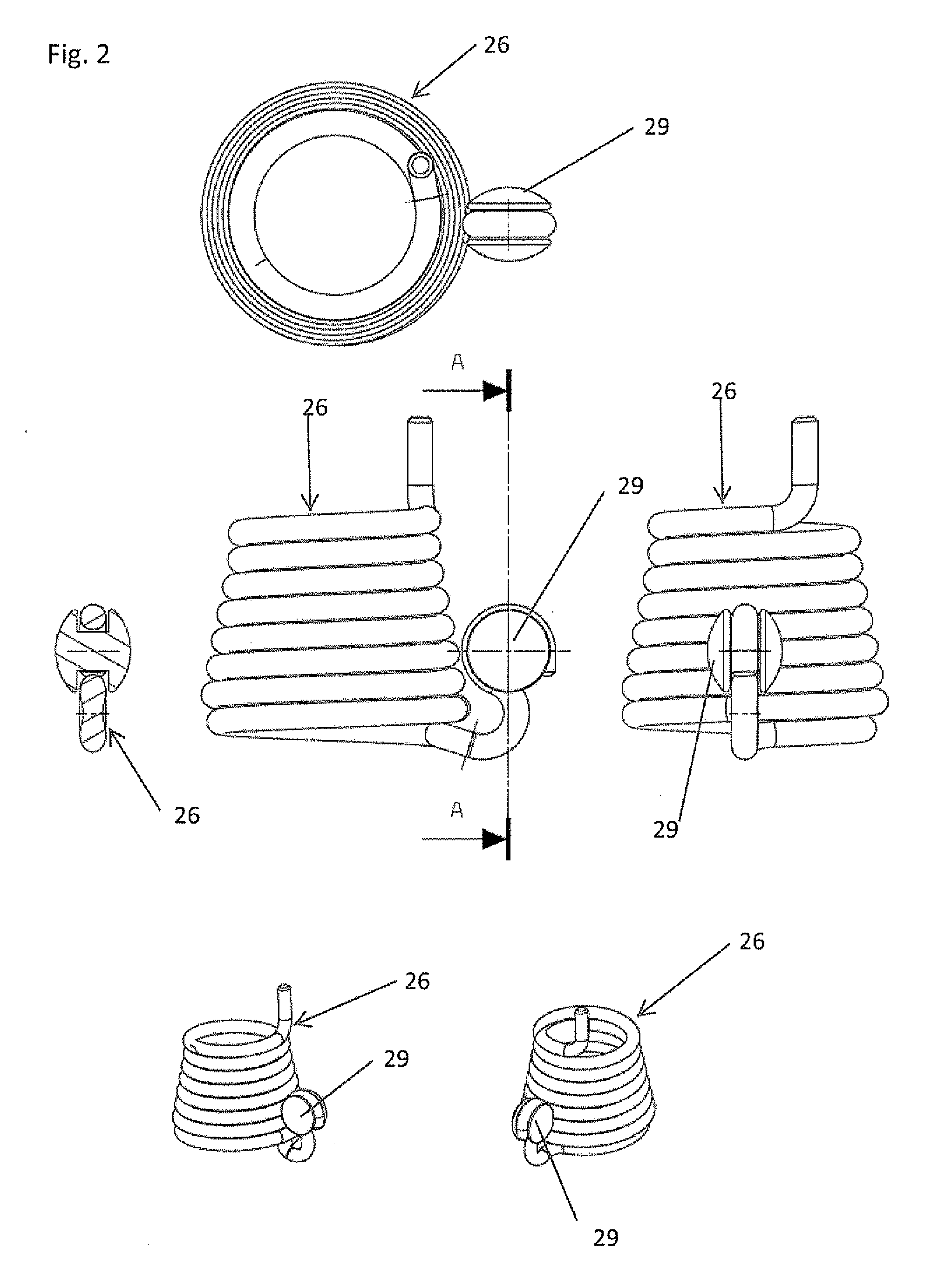
[0026]From the inner wall of the housing 10 there emanates a bearing pin 14, which is surrounded by a likewise substantially housing-fixed spring housing 15 for a spiral starter spring 16 clamped in on one end at the edge of the spring housing 15. This starter spring 16 serves as retraction spring for the cable sheave or cable drum 17.

[0027]The cable sheave or cable drum 17 has a pin on the rear side, which protrudes into the spring housing 15 through a centre bore of said spring housing and comprises an ax...


PUM


Abstract

A starting device for at least one combustion engine, in particular cable pull starting device for at least one two-stroke or four-stroke engine, with at least one cable sheave or cable drum rotatably mounted in a housing, which for generating a driving fork for a crankshaft can be put into rotary motion by means of at least one starter handle or pulling handle via at least one force transmission means, in particular via a starter cable or pulling cable and is connected to at least one driving member, in particular to at least one pawl driver via at least one elastic coupling element, by means of which the driving torque can be transmitted to the crankshaft, the coupling link having two ends, wherein an end is in engagement with the driving member and another end with the cable sheave or the cable drum.

Description

[0001]The invention relates to a starting device for at least one combustion engine, in particular cable pull starting device for at least one two-stroke or four-stroke engine, with at least one cable sheave or cable drum rotatably mounted in a housing, which for generating a drive torque for a crankshaft can be put into rotary motion by means of at least one starter handle or pulling handle via at least one force transmission means, in particular via a starter cable or pulling cable and via at least one elastic coupling link is connected to at least one driving member, in particular to at least one pawl driver, by means of which the drive torque can be transmitted to the crankshaft, the coupling member having two ends, wherein an end is engaged with the driving member and another end with the cable sheave or the cable drum.PRIOR ART[0002]The operation of a starting device for a combustion engine, in particular a cable pull starting device for a combustion engine, in particular for ...

Claims


Application Information

Patent Timeline
Patent Type & Authority Applications(United States)
IPC IPC(8): F02N1/00
CPCF02N3/02F02N15/065F02N15/063F02N5/02
Inventor WENCKEL, MATHIASZIEGS, CARSTEN
Owner MAKITA CORP
Why Eureka
Try Eureka