Controlling valve

Inactive Publication Date: 2009-02-19
HIGHPLUS INT
View PDF9 Cites 9 Cited by
  • Summary
  • Abstract
  • Description
  • Claims
  • Application Information

AI Technical Summary

Benefits of technology

[0016]To overcome the disadvantages as aforementioned of the conventional controlling valve, the

Problems solved by technology

However, the infrared-ray controlling switch has disadvantages.
Because the time to supply water of infrared-ray controlling switch is limited, the user is unable to finish washing.
Further, the reaction of the infrared-r

Method used


Image

  • Controlling valve
  • Controlling valve
  • Controlling valve

Examples


Embodiment Construction

[0043]

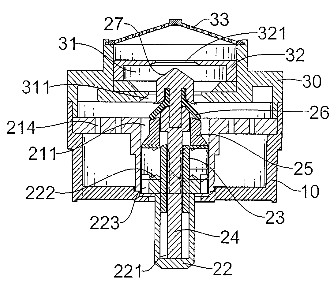
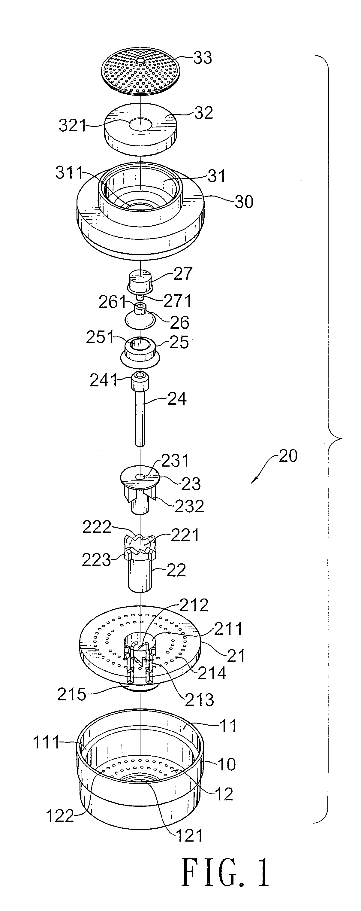
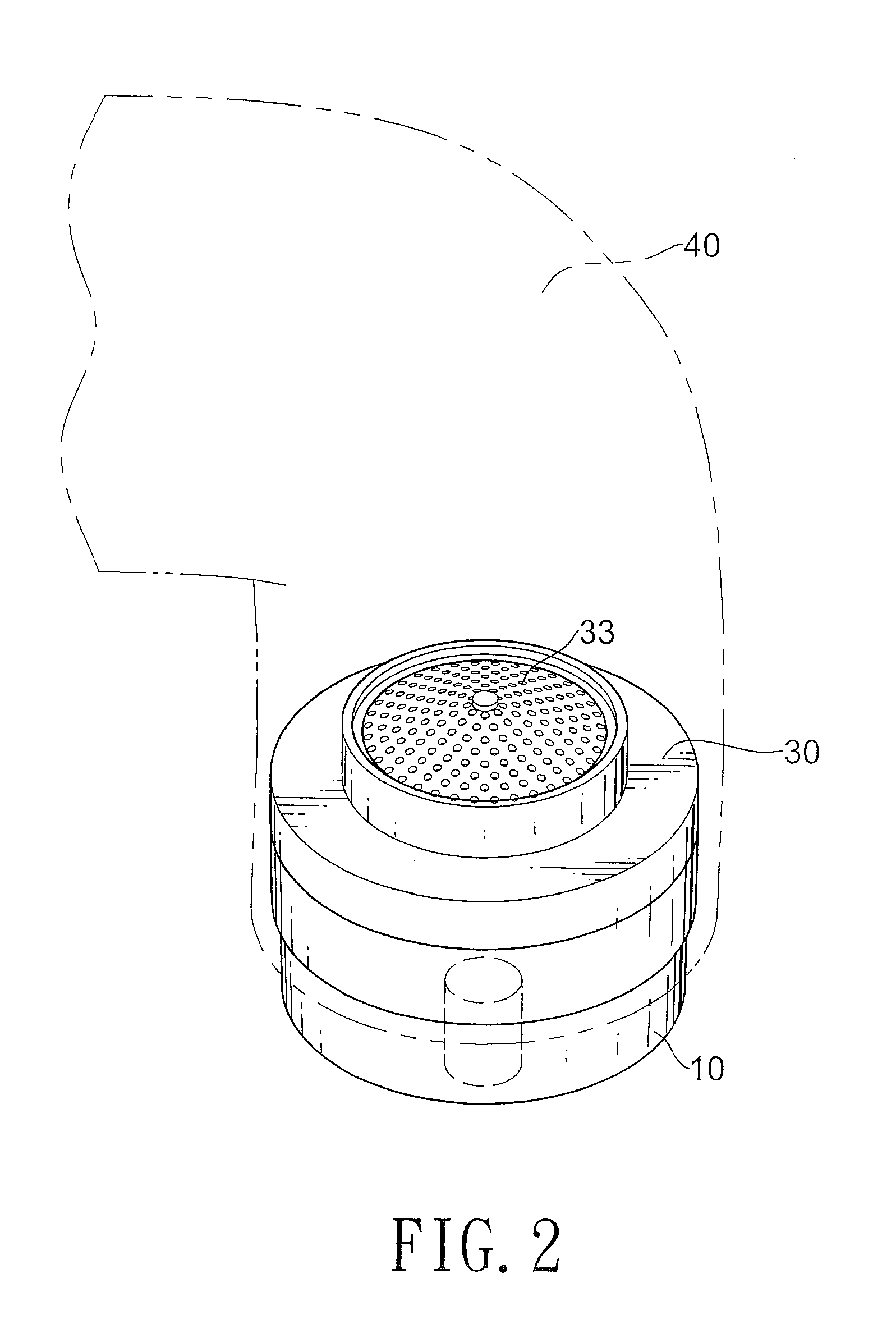
(10): sleeve(11): opening(111): inner flange(12): bottom cap(121): rod bore(122): water outlet(20): control valve group(21): valve seat(211): through hole(212): inclined edge(213): guiding channel(214): water bore(215): cylinder(22): pushing rod(221): mounting cavity(222): inclined edge(223): guiding protrusion(23): abutting seat(231): through hole(232): abutting protrusion(24): connecting rod(241): connecting hole(25): pushing seat(251): aperture(26): valve body(261): aperture(27): closed head(271): protruding rod(30): end cap(31): mounting cavity(311): water bore(32): outer sheet(321): flowing bore(33): filter(40): faucet(50): barrel(51): top recess(52): through hole(53): bottom recess(60): control valve group(61): spindle(611): closed head(612): protruding rod(613): side wing(62): valve seat(621): protruding end(622): inclined edge(623): guiding channel(624): flowing bore(63): pushing rod(631): mounting cavity(632): pushing channel(64): abutting rod(641): receiving hole(642...


PUM

PropertyMeasurementUnit
Pressureaaaaaaaaaa

Abstract

A controlling valve includes an outer sheet, an end cap and a control valve group. The control valve group is disposed between a flowing bore in the outer sheet and a water bore in the end cap. The controlling water valve is connected with the outlet of a water tube. When the control valve group is pushed upwards, the water bore in the end cap and the flowing bore in the outer sheet are closed in a predetermined sequence, then the water in the tube will not flow out. When the control valve group is pushed downwards, the flowing bore in the outer sheet and the water bore in the end cap are opened, then the water will flow out. When the water is stopped, the occurring positive or negative pressure wave is lowered, and then the vibration and the raspy noise will be avoided.

Description

BACKGROUND OF THE INVENTION[0001]1. Field of the Invention[0002]The present invention relates to a controlling valve, especially to a structure that is pushed to close the valve.[0003]2. Description of the Prior Arts[0004]Infrared-ray controlling switches are representative of the water switches on sale presently. When washing, the user's hand needs to be put at a certain position to switch on the infrared-ray controlling switch. Then the faucet starts to supply water. However, the infrared-ray controlling switch has disadvantages. Because the time to supply water of infrared-ray controlling switch is limited, the user is unable to finish washing. The user needs to switch on the infrared-ray controlling switch once again to finish washing. Further, the reaction of the infrared-ray controlling switch is not sensitive enough so the infrared-ray controlling switch is only switched on when the user puts the hand at the certain position. To solve the aforementioned problem, the conventio...

Claims


Application Information

Patent Timeline
IPC IPC(8): F16K1/00
CPCE03C1/08E03C2001/026F16K47/02F16K31/58F16K31/52433Y10T137/9464B05B1/32F16K31/52408
Inventor KAO, YU-YUEHKAO, CHIH-HUNG
Owner HIGHPLUS INT
Why Eureka
Try Eureka