Frac water heating system and method for hydraulically fracturing a well

a heating system and hydraulic fracturing technology, applied in the direction of lighting, heating apparatus, wellbore/well accessories, etc., can solve the problems of affecting the effectiveness of the heating facility, the construction of a permanent heating facility at the well site is not cost-effective, and the treatment fluid quantity is large, so as to achieve safe and continuous heating large quantities of treatment fluids

Inactive Publication Date: 2014-05-29
CHANDLER RONALD L
View PDF14 Cites 116 Cited by
  • Summary
  • Abstract
  • Description
  • Claims
  • Application Information

AI Technical Summary

Benefits of technology

[0019]The present invention overcomes many of the disadvantages of prior art mobile oil field heat exchange systems by providing a self-contained, frac-water heating system that is capable of safely and continuously heating large quantities of treatment fluids at remote locations in severely cold weather or at high altitude. In one embodiment, the present invention is disposed on a trailer rig and includes a closed-bottom firebox having a forced-air combustion and cooling system. The rig also includes integral fuel tanks, hydraulic and pneumatic systems for operating the rig at remote operations in all-weather environments. In a preferred embodiment, the frac-water heating system is used to heat treatment fluid on-the-fly (i.e., directly from the supply source to the well head) to complete hydraulic fracturing operations.

Problems solved by technology

Consequently, the construction of a permanent heating facility at the well site is not cost effective.
While such conventional gas-fired heat sources are adequate for performing many oil field servicing tasks, they exhibit a number of inherent drawbacks.
These inherent limitations significantly impact their effectiveness in performing certain heating operations at remote oil field work sites.
For example, frac jobs typically require the production of massive volumes of heated water.
While conventional gas-fired heat sources are certainly capable of heating fluids such as water, they are poorly suited to heating in a timely manner large volumes of continuously flowing water in many commonly occurring climactic and atmospheric conditions.
Moreover, the logistics involved in conducting such heating operations at remote work sites negatively impacts the cost efficiencies of such a system.
Thus, conventional gas-fired heating units often lack sufficient heating capacity to produce sufficient quantities of heated water rapidly enough for the required operation to be completed.
Needless to say, the logistics involved with providing additional holding tanks at the remote work site and the additional costs incurred in overheating or reheating the supply water negatively impacts the efficiency of the overall operation.
While the technique of overheating and stockpiling supply water can ameliorate some the shortcomings in the heating capacity of conventional gas-fired heat sources, in certain circumstances (e.g., severely cold weather or high altitude) it is inadequate.
First, the temperature change requirement for the system is simply greater in colder weather.
Thus, it takes longer for the conventional gas-fired heating unit to preheat the supply water.
The problem is further compounded by the fact that the stockpiled preheated water cools more rapidly in colder weather.
Thus, at higher altitudes the heating capacity of conventional gas-fired heat sources is further reduced.
In addition, propane gas requires large and heavy high-pressure fuel tanks for its transport to remote sites.
The size of such high-pressure fuel tanks is, of course, limited by the size of existing roads.
Furthermore, there are several safety concerns which must be taken into consideration when using conventional gas-fired heat sources.
An open flame at the well site poses a substantial risk of explosion and uncontrolled fire, which can destroy the investment in the rig and injure or even cost the lives of the well operators.
Moreover, open flame burners are particularly susceptible to erratic burning or complete blow-out in gusty wind conditions.
While safety concerns are of overriding importance, compliance with the no open-flame regulations requires additional time and expense to conduct heated fluid well treatments.

Method used


Image

  • Frac water heating system and method for hydraulically fracturing a well
  • Frac water heating system and method for hydraulically fracturing a well
  • Frac water heating system and method for hydraulically fracturing a well

Examples


embodiment 100

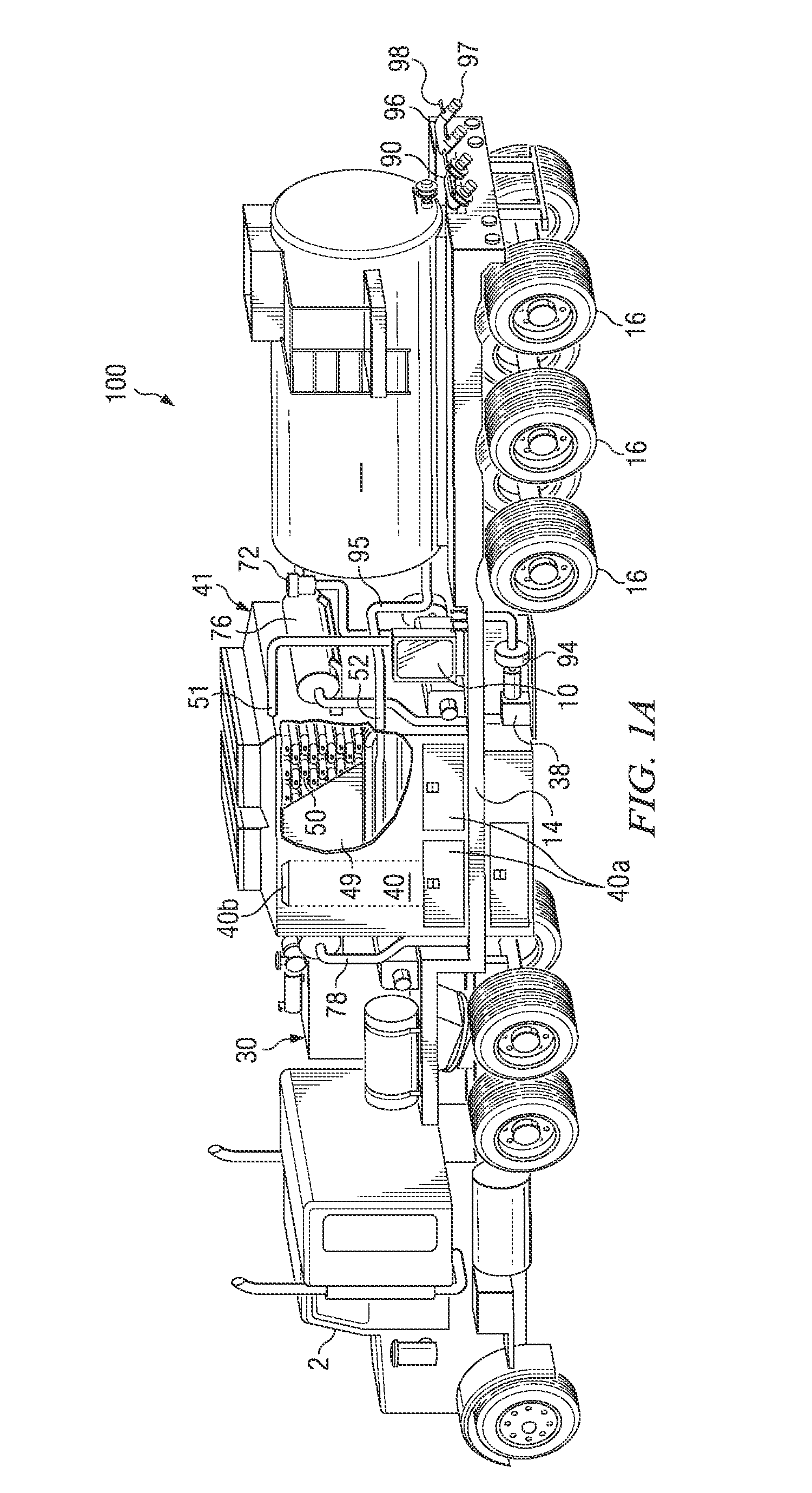
[0060]As shown in the Figures and schematically depicted in FIGS. 7A and 8A, in one embodiment the fuel system includes a fuel tank 20, which is configured near the rear or back end of the trailer 14. The fuel tank 20 is typically unpressurized and used to store the liquid fuel used by the multiple burner assemblies 60 configured in the firebox 40. In the depicted embodiment 100, the fuel tank 20 is unpressurized and can hold up to 60 bbl. of diesel fuel. The fuel system also includes an unpressurized fuel line 21, which supplies fuel from the fuel tank 20 to the intake of a fuel pump 22. The fuel pump 22 boosts the fuel pressure and directs it to the multiple burner assemblies 60 by means of a pressurized fuel line 26. In one embodiment, the fuel pump 22 boosts the fuel pressure to approximately 50-100 psi, preferably 60 psi.

[0061]The liquid fuel system also includes a pressure relief valve 24 in fluid communication with the pressurized fuel line 26. The pressure relief valve 24 pe...

first embodiment

[0077]The firebox 40 also includes a plurality of burner assemblies 60, which are configured in the lower side of the firebox 40. As will be subsequently described in greater detail, each of the burner assemblies 60 are connected to a fuel system and a pressurized air supply. For example, FIGS. 7A and 8A schematically depicts a first embodiment, which features oil-fired burner assemblies 60 connected to a fuel oil supply system. Liquid fuel is supplied to each burner assembly 60 via the metered pressurized fuel line 28. Similarly, pressurized air for combustion is supplied to each burner assembly 60 via a primary air conduit 78c. The pressurized air and fuel are combined in the burner assembly 60 and directed through an atomizer nozzle 64, which projects an atomized air-fuel spray into the firebox 40 where it is combusted. Each burner assembly 60 is configured in the lower side of firebox 40 so as to initially generate a substantially horizontal combustion flow within the firebox 40...

second embodiment

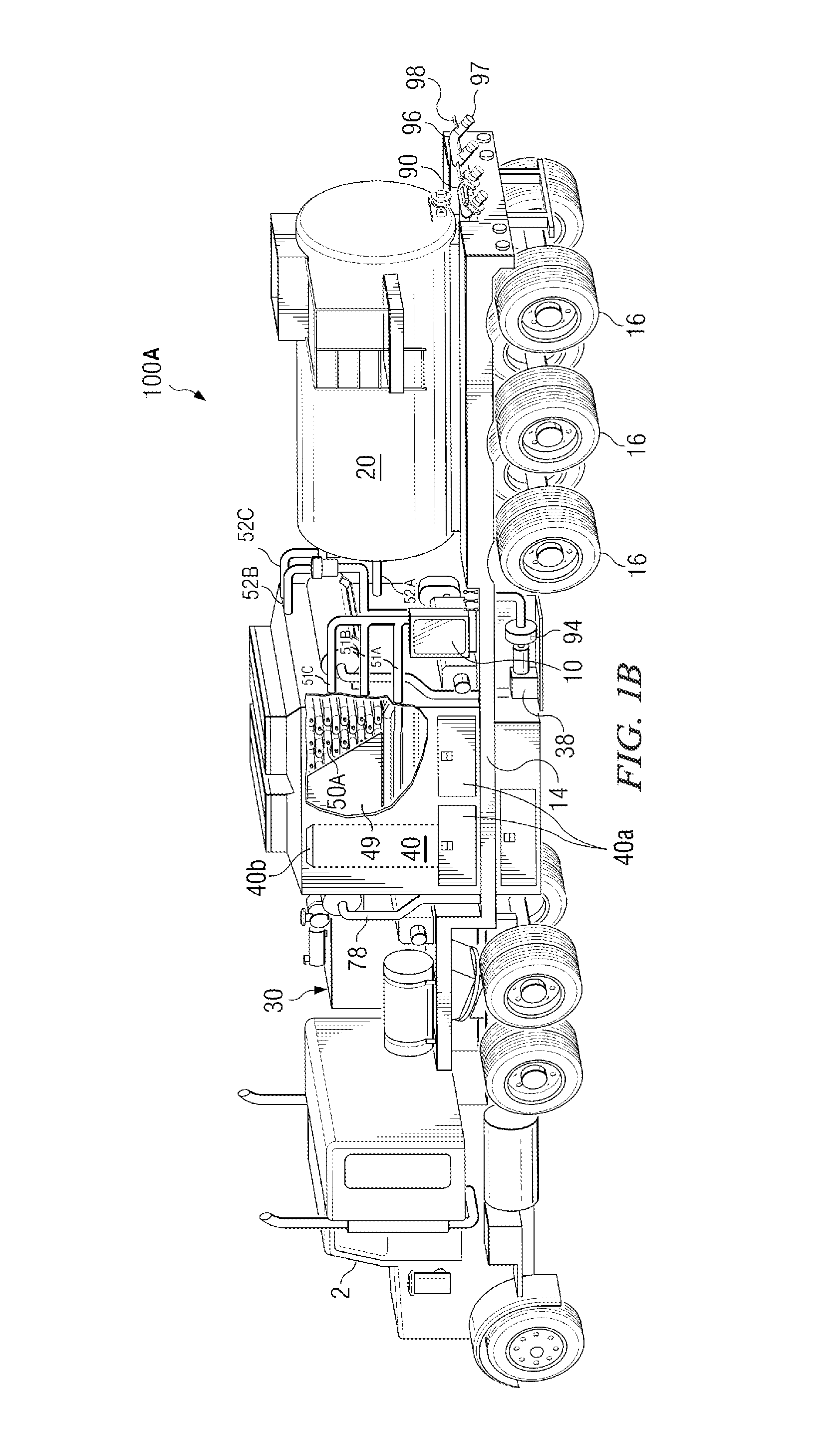
[0078]Similarly, FIGS. 7B and 8B schematically depicts a second embodiment, which features gas-fired burner assemblies 60 connected to a gas fuel supply system. Flammable gas fuel (e.g., LPG or natural gas) is supplied to each gas-fired burner assembly 60 via the metered pressurized gas fuel line 28A. Similarly, pressurized air for combustion is supplied to each gas-fired burner assembly 60 via a primary air conduit 78c. The pressurized air and fuel are combined in the burner assembly 60 and directed through a mixer nozzle 64A, which projects an air-gas fuel spray into the firebox 40 where it is combusted. Each gas-fired burner assembly 60 is configured in the lower side of firebox 40 so as to initially generate a substantially horizontal combustion flow within the firebox 40. Each gas-fired burner assembly 60 includes self-contained controls for adjusting the gas fuel-air mixture and an ignition mechanism for initially igniting the gas fuel-air mixture. In a preferred embodiment, t...


PUM


Abstract

The present invention overcomes many of the disadvantages of prior art mobile oil field heat exchange systems by providing an improved frac water heating system. The present invention is a self-contained unit which is easily transported to remote locations. In one embodiment, the present invention includes a single-pass tubular coil heat exchanger contained within a closed-bottom firebox having a forced-air combustion and cooling system. In another embodiment, the present invention includes multiple, single-pass heat exchanger units arranged in a vertically stacked configuration. The rig also includes integral fuel tanks, hydraulic and pneumatic systems for operating the rig at remote operations in all weather environments. In a preferred embodiment, the improved frac water heating system is used to heat water on-the-fly (i.e., directly from the supply source to the well head) to complete hydraulic fracturing operations. The present invention also includes systems for regulating and adjusting the fuel/air mixture within the firebox to maximize the combustion efficiency. The system includes a novel hood opening mechanism attached to the exhaust stack of the firebox.

Description

CROSS-REFERENCE TO RELATED APPLICATION[0001]This application is a continuation-in-part application of U.S. application Ser. No. 13 / 897,883 filed May 20, 2013, which is a divisional application of U.S. application Ser. No. 12 / 352,505 (now U.S. Pat. No. 8,534,235) filed Jan. 12, 2009, which claims the benefit of and priority to a U.S. Provisional Patent Application No. 61 / 078,734 filed Jul. 7, 2008, the technical disclosure of which is hereby incorporated herein by reference.[0002]This application is related to the following copending US Patent Applications, which are incorporated by reference herein in their entirety:[0003]U.S. patent application Ser. No. 14 / ______, (Attorney Docket No. DCHAN.0101DIV-CIP1), “Frac Water Heating System and Method for Hydraulically Fracturing a Well,” filed Jan. 31, 2014.[0004]U.S. patent application Ser. No. 14 / ______, (Attorney Docket No. DCHAN.0101DIV-CIP2), “Frac Water Heating System and Method for Hydraulically Fracturing a Well,” filed Jan. 31, 20...

Claims


Application Information

Patent Timeline
Patent Type & Authority Applications(United States)
IPC IPC(8): F24H1/06E21B43/267E21B43/26
CPCF24H1/06E21B43/267E21B43/26F24H1/08F24H1/40F24H9/2035F28D7/0066F28D7/02F28D7/08F24H1/43F28F9/26E21B43/2607
Inventor CHANDLER, RONALD L.
Owner CHANDLER RONALD L
Why Eureka
Try Eureka