Infusible unidirectional fabric

a technology of unidirectional fabrics and fabrics, applied in the direction of mechanical equipment, machines/engines, transportation and packaging, etc., can solve the problems of reducing the maximum achievable fiber volume fraction of a composite made with such reinforcements, not offering any improvement in mechanical properties, and typically imparting performance penalties on the final composite system

Inactive Publication Date: 2014-05-29
MILLIKEN & CO
View PDF3 Cites 51 Cited by
  • Summary
  • Abstract
  • Description
  • Claims
  • Application Information

AI Technical Summary

Problems solved by technology

These fabric forms typically impart performance penalties on the final composite system.
The stitch yarns typically create a separation or gap between rovings or tows within a fabric and between layers of fabric while not offering any improvement in mechanical properties.
Furthermore, the gaps created by the presence of the stitch yarns reduce the maximum achievable fiber volume fraction of a composite made with such reinforcement.
Finally, the fiber waviness negatively impacts several structural properties of composites reinforced with such systems such as tensile modulus and compression strength.

Method used


Image

  • Infusible unidirectional fabric
  • Infusible unidirectional fabric
  • Infusible unidirectional fabric

Examples


example 1

[0108]An unsaturated polyester control sample was made using the sample layup procedure using the 090 fabric and the ±45 fabric. The stacked textiles were infused in a standard vacuum infusion apparatus at a vacuum of less than 50 mbar with unsaturated polyester resin (Aropol Q67700 available from Ashland) and 1.5 parts per hundred resin (phr) methyl ethyl ketone peroxide (MEKP). The resin flow direction was along the 0° direction of the 090 fabric. The panel was cured at room temperature for more than 8 hours and further post cured at 80° C. for more than 4 hours. Fatigue testing of the unmodified glass reinforced unsaturated polyester composite at R=0.1 with a load of 1450 N / mm of specimen gage section width measured a lifetime of approximately 1×10⁴ cycles.

[0109]Example 2 to Example 7 showed how the film forming preventing agents affect the infusibility of the fiber fabric. The fiberglass fabrics used in Examples 2-6, and 8 were in small widths so will be referred to herein as fi...

example 2

[0110]A fiberglass tape was made in the following manner. First, a 9600 Tex fiberglass tow from PPG (HYBON® 2026) was spread into a 20 mm wide tape by a fiber tow spreading device. Next, four of the 20 mm wide tapes were combined and aligned in the same direction to form a 40 mm wide tape with twice the original tape thickness. A SBR latex (GENCAL® 7555 from OMNOVA) was mixed with water at a SBR latex to deionized water ratio of 1:4. The fiber tape was then dipped in the coating mixture and dried in an oven at 150° C. for 30 minutes. Next, the fiber tape was washed using deionized water and dried in oven at 150° C. for 15 minutes.

example 3

[0111]A 40 mm wide, fiberglass tape was made using the same fiberglass materials and process as Example 2. A SBR latex (GENCAL® 7555 from OMNOVA) was mixed with water and glycerin at a SBR latex to deionized water to glycerin ratio of 1:2:2. The fiber tape was dipped in the coating mixture and dried in an oven at 150° C. for 30 minutes. Next, the fiber tape was washed by deionized water and dried in oven at 150° C. for 15 minutes.


PUM

PropertyMeasurementUnit
widthaaaaaaaaaa
volume fractionaaaaaaaaaa

Abstract

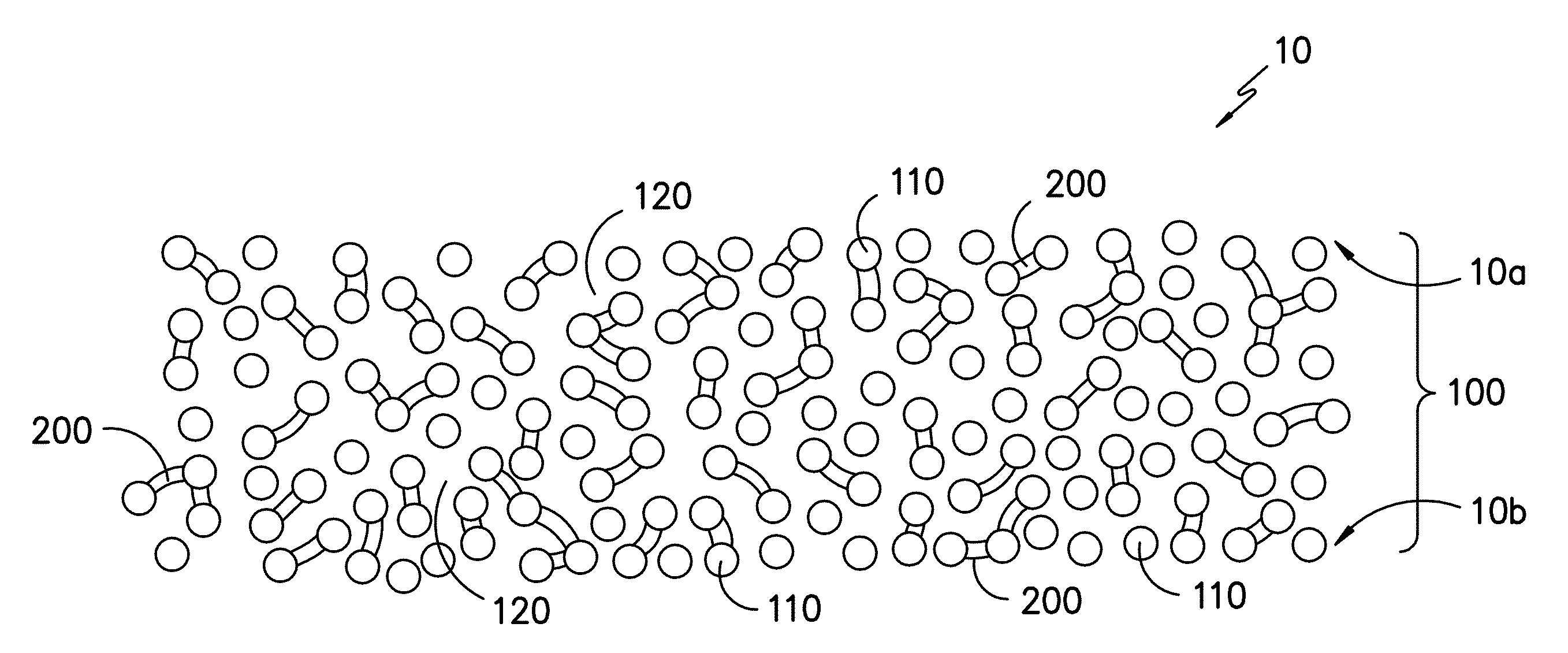
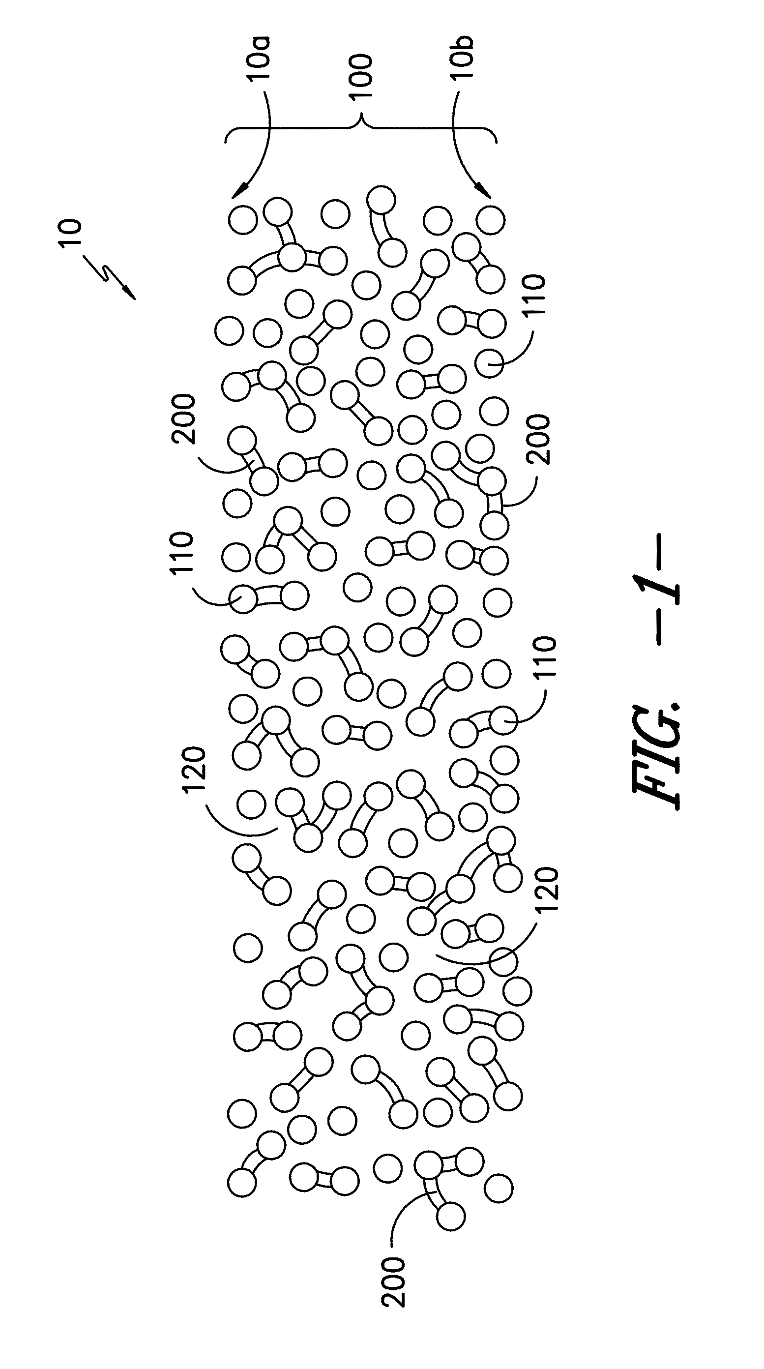
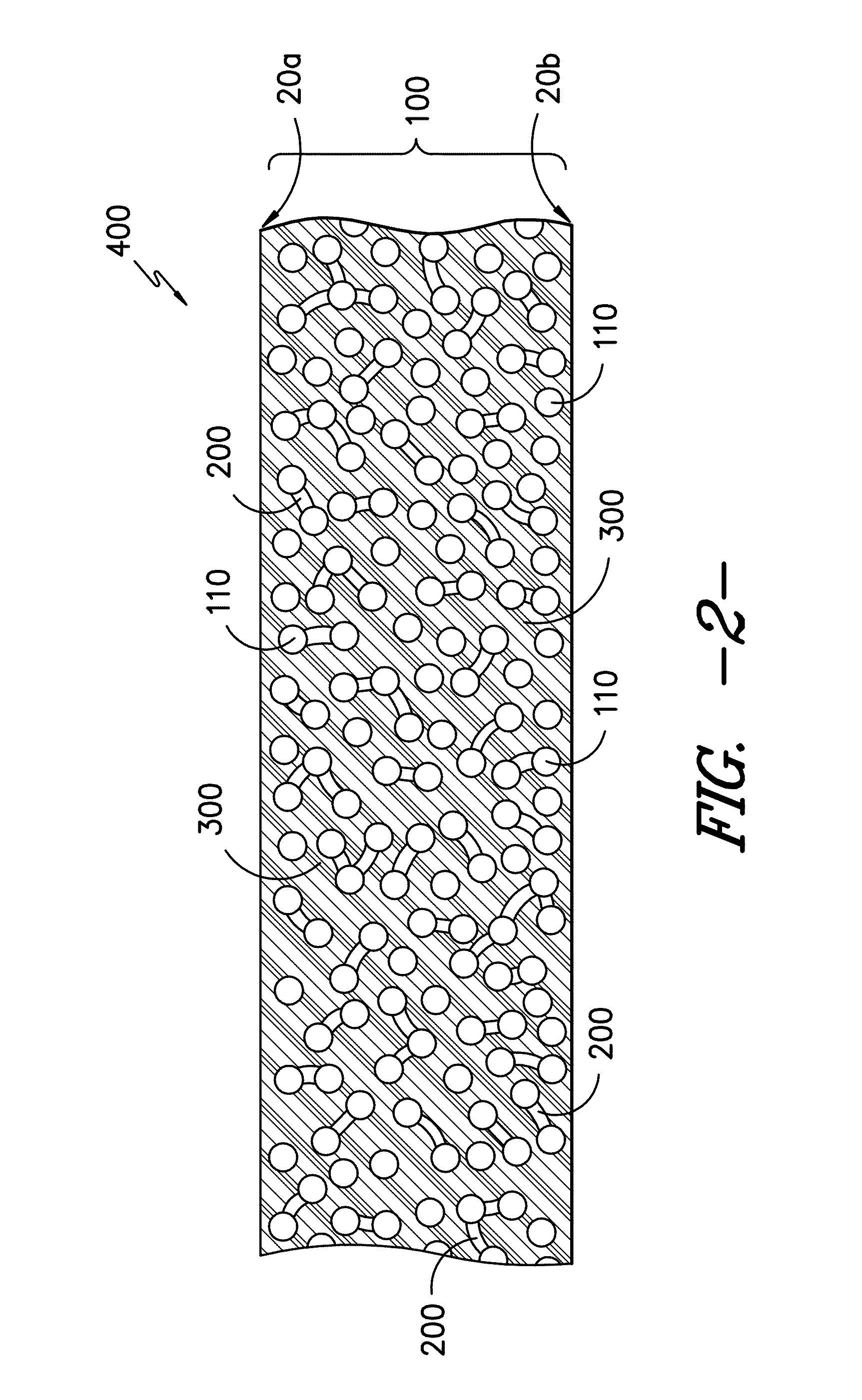
An infusible, unidirectional fabric containing a plurality of unidirectional fibers spaced uniformly in the unidirectional fabric, a plurality of bridges, and a plurality of void spaces between the unidirectional fibers. Each bridge is connected to at least 2 unidirectional fibers and at least 70% by number of fibers have at least one bridge connected thereto forming a bridged network of unidirectional fibers. The void spaces are interconnected and the fabric has a volume fraction of voids of between about 8 and 70%, a volume fraction of fibers of between about 35 and 85%, and at least 50% by number of the bridges have a bridge width minimum less than about 2 millimeters.

Description

RELATED APPLICATIONS[0001]This application claims priority to U.S. provisional application 61 / 730,677, filed Nov. 28, 2012, the contents of which are incorporated herein by reference in their entirety.FIELD OF THE INVENTION[0002]The present invention generally relates to infusible, unidirectional fabrics.BACKGROUND[0003]The development of more structurally efficient composite materials enables higher performance and more cost competitive solutions across a range of markets which use these materials. The traditional forms used for introducing dry fibers such as glass roving or carbon tow into a composite system are fabrics such as woven fabrics (having crimping) or multi-axial knit fabrics (with minimal crimping). These fabric forms typically impart performance penalties on the final composite system.[0004]Composites reinforced with woven fabrics are known to exhibit lower modulus and strength due to the extensive fiber crimping which occurs as opposing direction fibers cross over ea...

Claims


Application Information

Patent Timeline
Patent Type & Authority Applications(United States)
IPC IPC(8): D06M15/51F01D5/28
CPCF01D5/282D06M15/51B29C70/20D04H3/004D04H3/12B29B15/12B29C70/226Y10T428/24132Y10T428/249921D06M15/564
Inventor LI, XINJOHNSON, RYAN W.RUMLER, JOSEPH E.
Owner MILLIKEN & CO
Why Eureka
Try Eureka