Stride maker elliptical exercise apparatus

a technology of elliptical exercise and elliptical shaft, which is applied in the direction of sport apparatus, gymnastic exercise, frictional force resistor, etc., can solve the problems of numb toe and difficult startup

Active Publication Date: 2014-05-29
ESCHENBACH PAUL WILLIAM
View PDF4 Cites 23 Cited by
  • Summary
  • Abstract
  • Description
  • Claims
  • Application Information

AI Technical Summary

Benefits of technology

[0020]Load resistance is applied to the crank in this embodiment by a pulley which drives a belt to a smaller pulley attached to a flywheel supported by the framework. A tension belt covers the circumference of the flywheel to provide friction for load resistance on the intensity of exercise. A control system can adjust the tension on the tension belt through a load actuator shown in FIG. 1 to vary the intensity of exercise. It should be understood that other forms of load resistance such as magnetic, alternator, air fan or others may be applied to the crank. The control system also can adjust the incline of the tracks with a track actuator shown in FIG. 1 during operation to further change the intensity of exercise.

Problems solved by technology

The shorter stride lengths have pedals which follow up and down curves that are generally arcuate in shape causing difficult startup.
The longer stride lengths have pedals which follow closed loop curves having more of a banana shape than elliptical and the heel of the foot remains off the pedal for a significant part of the pedal cycle often resulting in numb toe.

Method used


Image

  • Stride maker elliptical exercise apparatus
  • Stride maker elliptical exercise apparatus
  • Stride maker elliptical exercise apparatus

Examples


Embodiment Construction

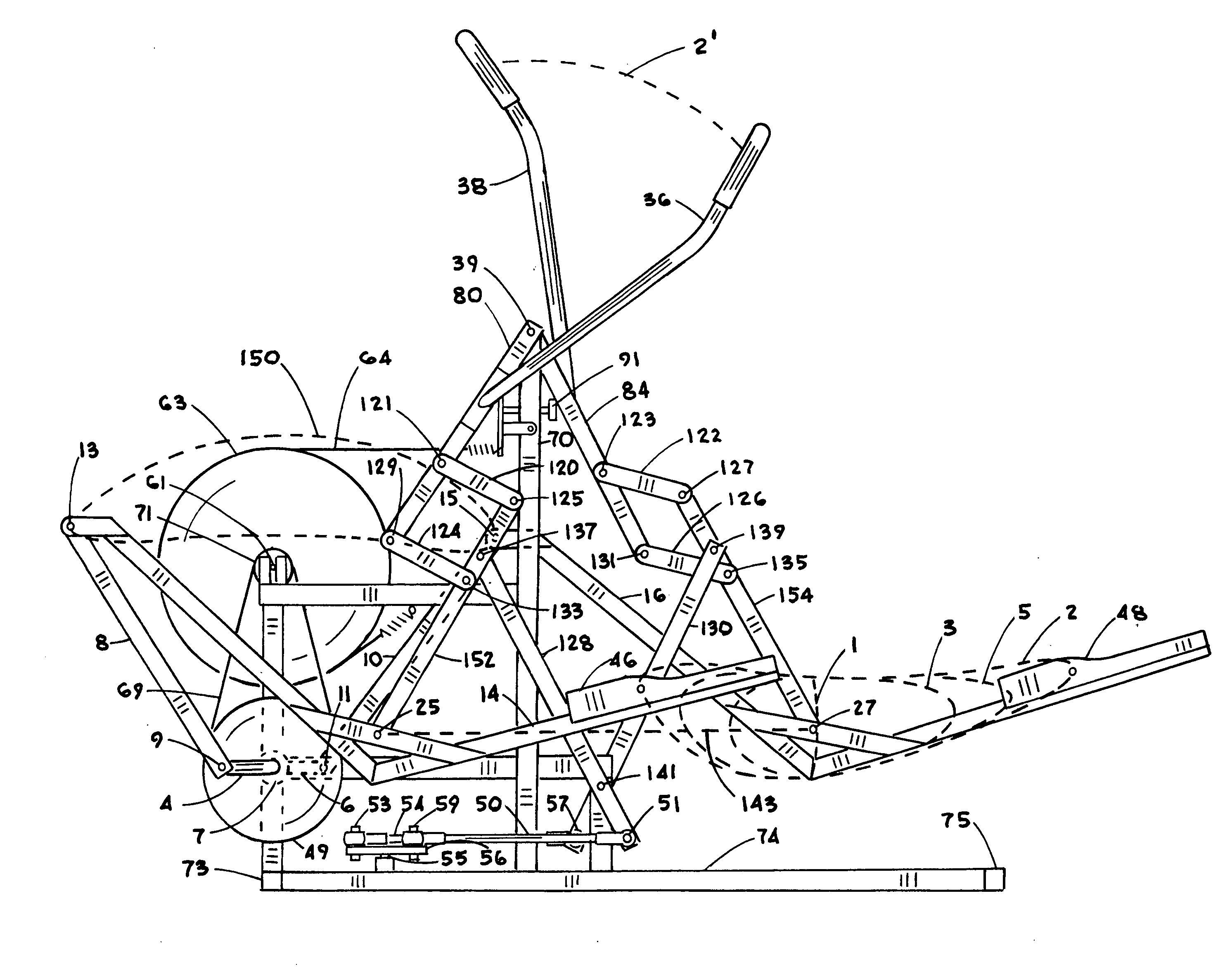
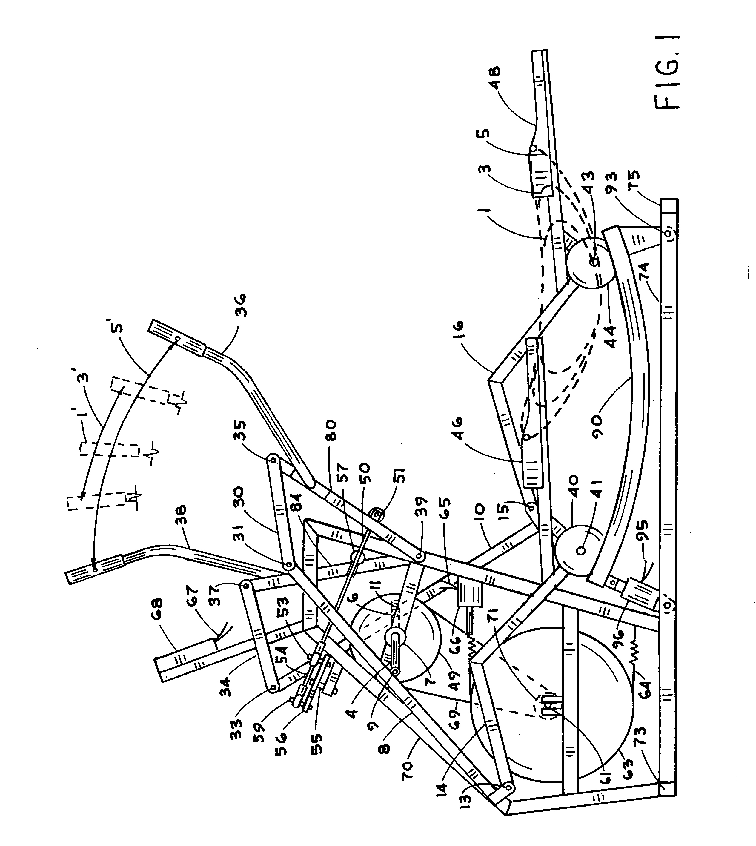
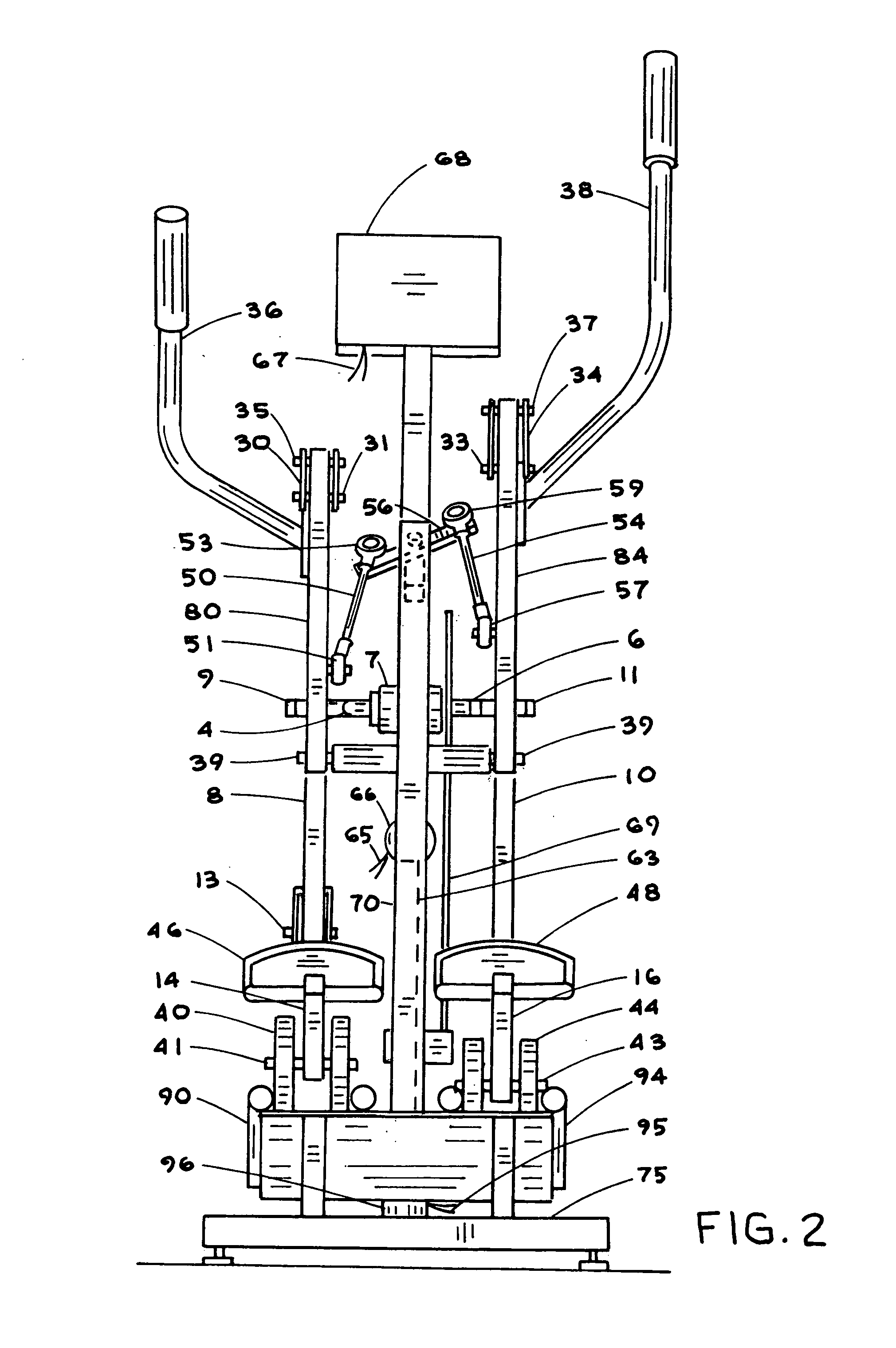
[0043]Referring to the drawings in detail, pedals 46 and 48 are shown in FIGS. 1 and 2 in forward and rearward positions of the preferred embodiment. Crank arms 4,6 rotate about pivot axis 7 on framework 70. Foot support members 14,16 have pedals 46,48 attached. Support links 8,10 are connected intermediate the ends to crank arms 4,6 at pivots 9,11 and to foot support members 14,16 at pivots 13,15. Tracks 90,94 are attached to frame members 74 at pivot 93 and to track actuator 96 which is also attached to framework 74. Rollers 40,44 are connected to foot support members 14,16 at pivots 41,43 and are in rollable contact with tracks 90,94.

[0044]Handles 36,38 are attached to handle supports 80,84 which are connected to framework 70 at pivot 39. Connector links 30,34 are connected to handle supports 80,84 at pivots 35,37 and to one end of support links 8,10 at pivots 31,33. Crossover member 56 is connected to framework 70 at pivot 55. Crossing links 50,54 are connected to crossover memb...


PUM


Abstract

The present invention relates to a standup exercise apparatus that simulates walking and jogging with arm exercise. More particularly, the present invention relates to an exercise machine having separately supported pedals for the feet and arm exercise coordinated with the motion of the feet where the pedal stride length is determined by the movements of an operator. Crank arms are positioned on the framework forward the operator at a height comparable to the pedals. Compound guides are used to achieve elliptical curve pedal paths.

Description

[0001]This application is a continuation-in-part of U.S. patent application Ser. No. 13 / 573,422 filed Sep. 14, 2012 which is a continuation-in-part of U.S. patent application Ser. No. 13 / 385,425 filed Feb. 21, 2012 which is a continuation-in-part of U.S. patent application Ser. No. 12 / 799,909 filed May 5, 2010, now U.S. Pat. No. 8,133,159, incorporating all of these by reference.BACKGROUND OF THE INVENTION[0002]1. Field[0003]The present invention relates to a standup exercise apparatus that simulates walking and jogging with arm exercise. More particularly, the present invention relates to an exercise machine having separately supported pedals for the feet and arm exercise coordinated with the motion of the feet where the pedal stride length is determined by the movements of an operator. Crank arms are positioned forward the operator at pedal height.[0004]2. State of the Art[0005]The benefits of regular exercise to improve overall health, appearance and longevity are well documented...

Claims


Application Information

Patent Timeline
Patent Type & Authority Applications(United States)
IPC IPC(8): A63B22/04
CPCA63B21/0053A63B21/0083A63B21/0088A63B21/015A63B21/225A63B22/001A63B22/0015A63B22/0023A63B22/0664A63B22/203A63B22/205A63B2022/0676A63B2022/0682A63B2022/206A63B22/0017
Inventor ESCHENBACH, PAUL WILLIAM
Owner ESCHENBACH PAUL WILLIAM
Why Eureka
Try Eureka