
Separation disc for a centrifugal separator and a method for manufacturing the separation disc

Active Publication Date: 2014-05-29
ALFA LAVAL CORP AB
View PDF9 Cites 12 Cited by
  • Summary
  • Abstract
  • Description
  • Claims
  • Application Information

AI Technical Summary

Benefits of technology

The invention provides a separation disc with small-sized spacing members that can be provided in greater number without blocking the flow of liquid mixture. The spacing members can be integrally formed with the material of the separation disc, which reduces the risk of uneven surfaces and produces a more reliable form on the spacing members. The separation disc can also comprise large-sized spacing members that support a greater portion of the forces in the disc stack. The invention is particularly useful for maintaining equidistant interspaces in a stack of thin separation discs.

Problems solved by technology

However, there's a lower limit as to how thin the separation discs can be made.
If the separation discs are made too thin, such strains would lead to material failure or permanent deformation.
Prior to this happening, there may be other problems with very thin separation discs.
As the separation discs are made thinner, they will exhibit a loss in rigidity and irregularities in their shape may begin to appear.
The thin separation discs may thereby flex and / or because of their irregular shaping give rise to unevenly sized interspaces in the stack of separation discs.
Consequently, different sized interspaces along the stack would cause uneven flow distribution, whereby certain interspaces are overloaded with flow, while other interspaces barely receive any flow at all.
Such uneven flow distribution will in turn cause a decrease in the separating efficiency of the disc stack.
This problem may also appear in each of the individual interspaces, wherein compressed parts barely receive any flow at all and consequently do not contribute to separating the liquid mixture.
Furthermore, as previously mentioned, and in particular in large size centrifugal separators, the separation discs can run the risk of touching each other in the compressed state.
This is typically also the point where said problems of low disc rigidity and / or irregular shaping becomes an issue.
Obviously the separation disc should thereby not be provided with any further (or small-sized) spacing members on the opposite (inner) surface area to the large-sized spacing member, in such a way that a faulty double spacing is caused by directly abutting spacing members of mutually adjacent separation discs in the stack.

Method used


Image

  • Separation disc for a centrifugal separator and a method for manufacturing the separation disc
  • Separation disc for a centrifugal separator and a method for manufacturing the separation disc
  • Separation disc for a centrifugal separator and a method for manufacturing the separation disc

Examples


first embodiment

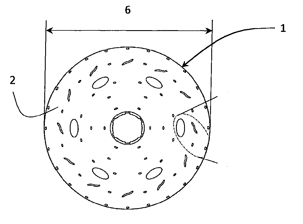
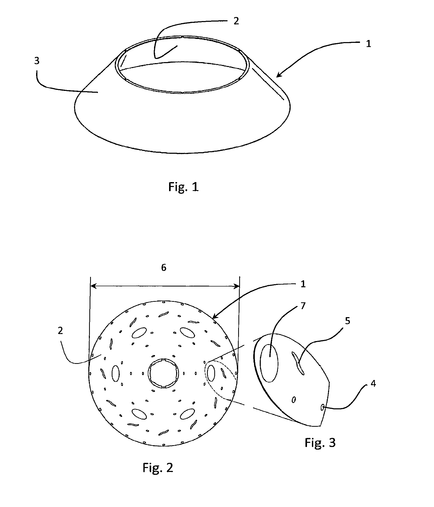
[0036]FIG. 2 shows an inner-surface-view of a separation disc according to the invention. Hence, an inner surface 2 of the separation disc 1 is shown which is provided with a plurality of spacing members 4, 5 which are also shown in FIG. 3. The spacing members 4 and 5 are formed in one piece with the (metal) material of the separation disc 1. This is achieved in a flow forming process described below.

[0037]Furthermore, as can be seen in FIG. 3, the spacing members 4 and 5 are of different shapes; a spot-formed spacing member 4 and an elongated spacing member 5. The diameter of the spot-formed spacing member 4 corresponds to its width. Hence, the diameter of the spot-formed spacing member is the same as its width. The elongated spacing member 5 however is several times longer than it is wide, and it is furthermore curved along its length. Both spacing members 4 and 5 in this embodiment each have approximately the same width of 1 mm. The length of the elongated spacing members 5 is ho...

second embodiment

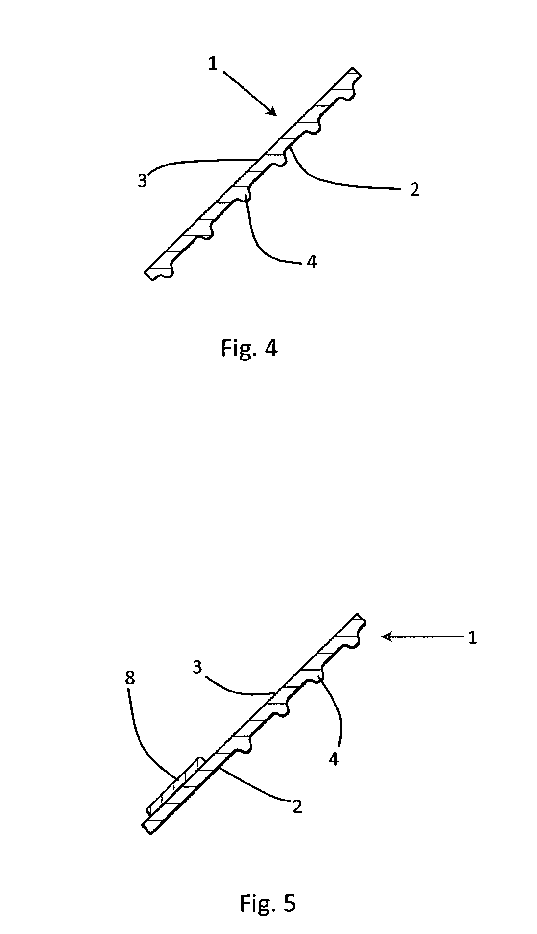
[0040]FIG. 4 shows a cross-section of said small-sized and spot-formed spacing members 4 on the inner surface 2 of the separation disc 1. As can be seen, the spacing members 4 are formed in one piece with the material of the separation disc 1. The presently utilized manufacturing techniques (or the flow forming technique) for producing separation discs 1 is the main reason why the integrally formed spacing members 4 are provided on the inner surface 2. However, they may as well be arranged on the outer surface 3 of the separation disc. The integrally formed spacing members 4 may for instance be provided on the outer surface 2 by a pressing technique. Furthermore, the inner surface 2 of the separation disc 1 is provided with the small-sized spacing members 4 only. Hence, no other spacing members (such as larger sized spacing members) are provided on the surface. However, the small-sized spacing members may also be combined with larger sized spacing member (i.e. having a larger width)...


PUM

PropertyMeasurementUnit
Diameteraaaaaaaaaa
Diameteraaaaaaaaaa
Lengthaaaaaaaaaa

Abstract

A separation disc for a centrifugal separator and a method for manufacturing the separation disc are disclosed. The separation disc is of metal material and adapted to be compressed in a stack of separation discs inside a centrifugal rotor for separating a liquid mixture. The separation disc has a truncated conical shape with an inner surface and an outer surface and a plurality of spacing members extending a certain height above at least one of the inner surface and the outer surface for providing interspaces between mutually adjacent separation discs in the stack. The spacing members are of such small size that each one of them has a width which is less than 2 mm along the surface of the separation disc. The surface of the separation disc is configured with a distribution pattern of the small-sized spacing members, in such a way as to provide equidistant interspaces in the compressed disc stack.

Description

TECHNICAL FIELD[0001]The invention relates to a separation disc for a centrifugal separator and a method for manufacturing the separation disc. In particular the invention relates to a separation disc made of metal material and which is adapted to be compressed in a stack of separation discs inside a centrifugal rotor for separating a liquid mixture, the separation disc having a truncated conical shape with an inner surface and an outer surface and a plurality of spacing members extending a certain height above at least one of the inner surface and the outer surface for providing interspaces between mutually adjacent separation discs in the stack.BACKGROUND ART[0002]Separation discs of metal are used in connection with relatively robust and large-sized centrifugal separators for separating liquid mixtures; wherein the separation discs are of relatively large size and exposed to both high centrifugal and liquid forces.[0003]The separation discs are stacked at a mutual distance to for...

Claims


Application Information

Patent Timeline
IPC IPC(8): B04B7/14
CPCB04B1/08B04B7/14B21D22/16
Inventor NILSSON, SVEN- KETHORWID, PETER
Owner ALFA LAVAL CORP AB
Learn More