Cleaning device and cleaning method

a cleaning device and cleaning method technology, applied in the direction of cleaning process and apparatus, chemical apparatus and processes, etc., can solve the problems of inability to use removers repeatedly, inconvenient cleaning methods, and inability to achieve high-speed cleaning, easy acceleration, and low air resistance

Inactive Publication Date: 2011-03-24
RICOH KK
View PDF9 Cites 10 Cited by
  • Summary
  • Abstract
  • Description
  • Claims
  • Application Information

AI Technical Summary

Benefits of technology

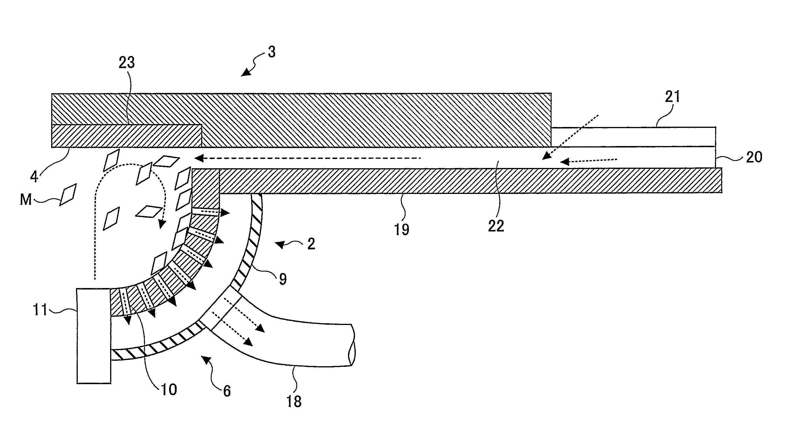
[0072]1. Ability to Fly Along with Air Flow (Ability to Fly at High Speed and to Make Complex Movements)
[0073]1-1. The mass of the flake-like cleaning medium M is very small relative to the air resistance. Therefore, when the force of an air flow is applied to a surface of the cleaning medium M with a large projected area, the cleaning medium M is easily accelerated by the air flow and flies.
[0074]1-2. The flake-like cleaning medium M has low air resistance in a direction forming a small projected area and therefore can maintain high-speed movement for a long distance when flying in that direction. The thickness of the cleaning medium M of this embodiment is preferably greater than or equal to 20 μm and less than or equal to 200 μm, and its surface area is preferably less than or equal to 100 mm2.
[0075]As the speed of the cleaning medi

Problems solved by technology

Since the pallet is repeatedly used for soldering processes, the flux accumulates to form a thick layer and becomes difficult to remove.
However, when photosensitive drums are recycled as raw materials, it is necessary to produce base tubes again from the raw materials.
Therefore, this method is not preferable in terms of energy consumption, effects on the environment, and production costs.
When a remover is used to remove a photosensitive layer of a photosensitive drum or a flux adhering to a pallet, the remover cannot be used repeatedly because resin dissolved in the remover may adhere again to the base tube or the pallet.
Therefore, this method is not

Method used


Image

  • Cleaning device and cleaning method
  • Cleaning device and cleaning method
  • Cleaning device and cleaning method

Examples


example 1

[0173]In example 1, a fusing roller of imagio Neo 300 (monochrome copier) was used as an object to be cleaned.

[0174]The pencil hardness of fluoroplastic forming the release layer of the fusing roller was about “F”.

[0175]Each object was cleaned for two minutes using arrays of air nozzles SL-920A of Silvent to jet compressed air and the pressure of the compressed air was maintained at 0.5 MPa.

[0176]In example 1, the following types of cleaning media M were used:

[0177](Example 1-1) polyethylene films (pencil hardness 6B or lower) with a thickness of 100 μm and dimensions of 5 mm by 5 mm

[0178](Example 1-2) PET films (pencil hardness H) with a thickness of 100 μm and dimensions of 5 mm by 5 mm

[0179](Example 1-3) acrylic resin films (pencil hardness 2H) with a thickness of 100 μm and dimensions of 5 mm by 5 mm

[0180](Example 1-4) flakes of SUS304 (pencil hardness 9H or higher) with a thickness of 100 μm and dimensions of 5 mm by 5 mm

[0181]As comparative examples, the object was cleaned by ...

example 2

[0191]Each object was cleaned for two minutes using arrays of air nozzles SL-920A of Silvent to jet compressed air and the pressure of the compressed air was maintained at 0.5 MPa.

[0192]In example 2, the cleaning media were repeatedly used without replacing them for multiple objects and the cleaning quality was evaluated in association with the number of objects processed.

[0193]In example 2, the following types of cleaning media M were used.

[0194](Example 2-1) polyethylene films (pencil hardness 6B or lower) with a thickness of 100 μm and dimensions of 5 mm by 5 mm

[0195](Example 2-2) PET films (pencil hardness H) with a thickness of 100 μm and dimensions of 5 mm by 5 mm

[0196](Example 2-3) acrylic resin films (pencil hardness 2H) with a thickness of 100 μm and dimensions of 5 mm by 5 mm

[0197](Example 2-4) flakes of SUS304 (pencil hardness 9H or higher) with a thickness of 100 μm and dimensions of 5 mm by 5 mm

[0198]Cleaning results are shown in table 2 below. Meanings of symbols used ...

example 3

[0200]In examples 3 and 4, a photosensitive layer (polycarbonate binder resin with pencil hardness F) of an organic photoreceptor (OPC) drum used in an electrophotographic device such as a copier or a laser printer was used as a deposit to be removed. However, the present invention may also be applied to a cleaning device for removing any other type of film-like deposit.

[0201]The type of cleaning media and the speed and flow rate of the air flow are appropriately determined according to the characteristics of the film-like deposit and the object to be cleaned.

[0202]Each object was cleaned for two minutes using arrays of air nozzles SL-920A of Silvent to jet compressed air and the pressure of the compressed air was maintained at 0.5 MPa.

[0203]In example 3, the following types of cleaning media M were used.

[0204](Example 3-1) polyethylene films (pencil hardness 6B or lower) with a thickness of 100 μm and dimensions of 5 mm by 5 mm

[0205](Example 3-2) PET films (pencil hardness H) with ...


PUM


Abstract

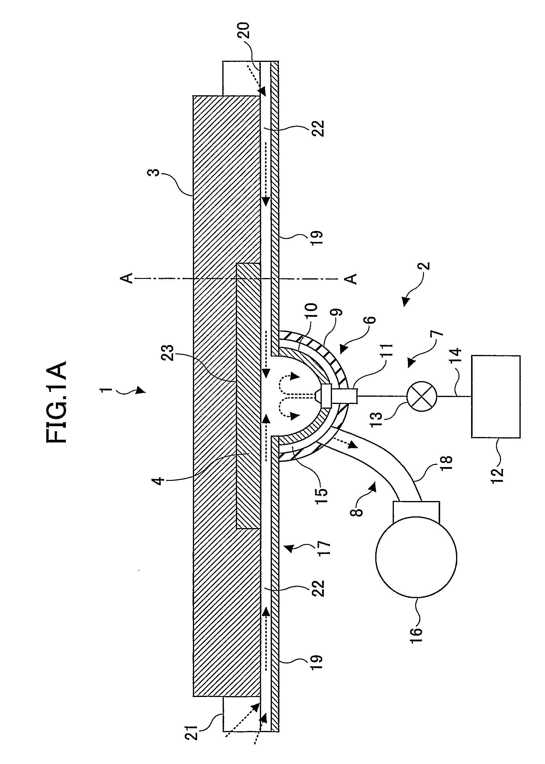
A cleaning device for removing a deposit adhering to an object to be cleaned is disclosed. The cleaning device includes a cleaning chamber forming a space for housing multiple cleaning media shaped like flakes; a circulating air-flow generating unit configured to generate a circulating air flow to cause the cleaning media to fly and repeatedly collide with the object in the cleaning chamber and thereby to remove the deposit adhering to the object; and a cleaning medium recycling unit configured to suction and remove the deposit adhering to the cleaning media that have collided with the object and thereby to recycle the cleaning media. The pencil hardness of the cleaning media is greater than the pencil hardness of the deposit.

Description

TECHNICAL FIELD[0001]A certain aspect of the present invention relates to a cleaning device and a cleaning method for removing a deposit adhering to an object using solid cleaning media.BACKGROUND ART[0002]Generally, in a soldering process, a viscous liquid called “flux” is sprayed onto a substrate to improve the wettability of solder. The flux adheres to a printed circuit board (PCB) or a jig called “pallet” for holding the PCB because of the heat of solder. Therefore, it is necessary to remove the adhering flux from the pallet.[0003]The pallet is now widely used in soldering processes and is made of an epoxy resin containing glass fibers. Since the pallet is repeatedly used for soldering processes, the flux accumulates to form a thick layer and becomes difficult to remove.[0004]Meanwhile, manufacturers of office equipment such as copiers and laser printers are actively engaged in recycling activities to achieve a resource recycling society. In the recycling activities, the manufac...

Claims


Application Information

Patent Timeline
IPC IPC(8): A47L7/00
CPCB08B5/02B08B7/02B08B7/00
Inventor SATOH, TATSUYAOKAMOTO, YOICHIFUCHIGAMI, AKIHIROTANEDA, YUUSUKE
Owner RICOH KK
Why Eureka
Try Eureka