
Permeable cement stone fracturing exploitation method for non-conventional oil and gas layer

a cement stone and fracturing technology, applied in the direction of fluid removal, climate sustainability, borehole/well accessories, etc., can solve the problems of short effective duration, high cost, and difficult detoxification of disposal, and achieve long effective duration of stimulation, large stimulation, and high effective permeability

Active Publication Date: 2018-08-23
SICHUAN XINGZHI ZHIHUI INTPROP OPERATION CO LTD +1
View PDF0 Cites 9 Cited by
  • Summary
  • Abstract
  • Description
  • Claims
  • Application Information

AI Technical Summary

Benefits of technology

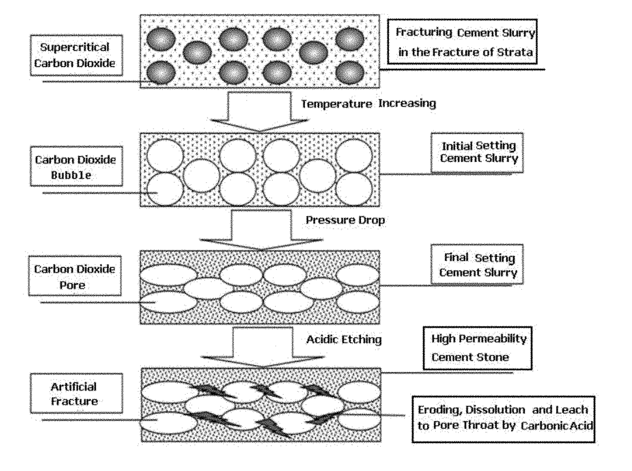
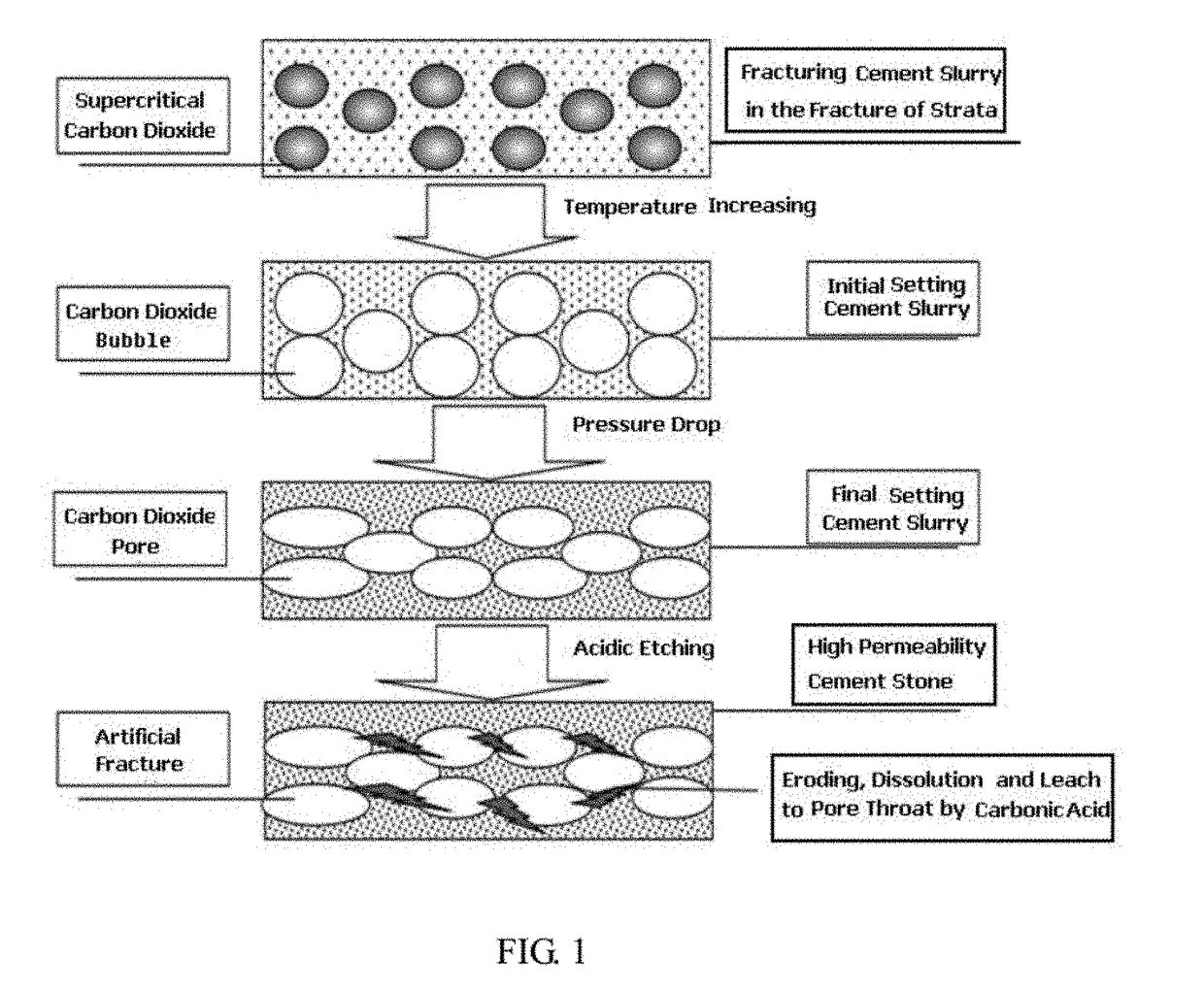
The present invention is a new and effective method for fracturing non-conventional oil and gas layers, such as tight oil and gas, shale gas, coal-bed methane, gas hydrate, etc. The method uses a second mixture of supercritical carbon dioxide (SC-CO2) and cement slurry to form permeable cement stone automatically, supporting and fixing the artificial fracture and the natural fracture of the oil and gas layer, and connecting the wellbore and the oil and gas layer effectively. This method mining oil and gas without using conventional devices, resulting in zero flow-back fluid, smaller amount of water and material, smaller equipment and area of well-site, lower cost, improved effect, better environmental benefit, and better adaptability.

Problems solved by technology

1. A large amount of fracturing fluid having poor compatibility with the strata is needed and tends to pollute the strata. Large amount of flow-back fluid with complex composition is left after fracturing, and detoxification of the disposal is very difficult and expensive, resulting in pollution of the environment.
2. The stimulation of oil and gas is poor. In conventional fracturing, there is only point contact between the fracture surface and the spherical ceramic proppant, which is easily crushed and embedded into the soft strata, resulting in short effective duration of stimulation. Moreover, as the proppants are separated from each other, small particles in the proppants tend to move and flow back, causing complex and dangerous issues such as blocking and abrading the pipeline system laid on the ground, under the ground and at the wellhead.
3. Large hydraulic horsepower is needed. For example, in a horizontal shale gas well with a vertical depth of 3000 meters and a horizontal length of 1000 meters, over 20,000 HHP of hydraulic horsepower is needed for the fracturing trucks in conventional staged fracturing operations.
4. Large well site is needed. Lots of conventional fracturing equipments and accessorial equipments are used to transport and store materials for fracturing, oil, proppant, water, etc., thus occupying large well site.
5. High risk of environmental damage. The conventional fracturing uses large-scale water-based fluid and proppant producing a mass of flow-back fluid after fracturing, causing costly disposal detoxification and reuse of the flow-back fluid and serious pollution to the natural environments such as water, land air, and so on. The massive fracturing using water-based fluid for coal-bed methane or gas hydrate in the shallow strata would bring geological disasters, such as land collapse, landslide, earthquake, etc.
6. High cost of exploitation. Using conventional fracturing stimulation in non-conventional oil and gas layer has the disadvantages of needing large amount of fracturing fluid, large hydraulic horsepower, large well site, high environmental expenses, and short effective duration of stimulation, resulting in high cost of exploitation, therefore limiting rich non-conventional oil and gas to be mined in an effective, environmentally friendly and massive way. The rich non-conventional oil and gas include tight oil and gas, shale gas, coal-bed methane, gas hydrate and etc.

Method used


Image

  • Permeable cement stone fracturing exploitation method for non-conventional oil and gas layer
  • Permeable cement stone fracturing exploitation method for non-conventional oil and gas layer
  • Permeable cement stone fracturing exploitation method for non-conventional oil and gas layer

Examples


Embodiment Construction

[0024]The present invention will now be described more specifically with reference to the following embodiments in combination with the drawings, but the present invention is not limited to the precise form disclosed.

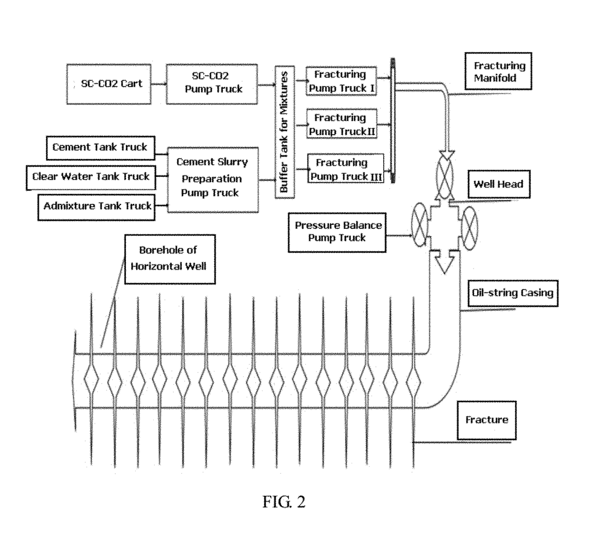
[0025]In one embodiment, a permeable cement stone fracturing exploitation method for a non-conventional oil and gas layer comprises the following complementary processes:

[0026]1) transporting, storing and pumping process for supercritical carbon dioxide: transporting the supercritical carbon dioxide to a well site by using a specialized tanker truck or a pipeline; storing the supercritical carbon dioxide at the well site under a supercritical state with a pressure higher than 7.38 Mpa and a temperature lower than 31.05° C.; and pumping and transporting the supercritical carbon dioxide by using one or more supercritical carbon dioxide pumps; wherein a critical condition of the supercritical carbon dioxide comprises a pressure higher than 7.38 Mpa and a temperature lower ...


PUM

PropertyMeasurementUnit
temperatureaaaaaaaaaa
horizontal lengthaaaaaaaaaa
vertical depthaaaaaaaaaa

Abstract

Disclosed is a permeable cement stone fracturing exploitation method for non-conventional oil and gas layer such as tight oil and gas, shale gas, coal-bed gas, combustible ice and so on. The method comprises the following complementary processes and embodiments: transporting, storing and pumping process for supercritical carbon dioxide; transporting, storing, preparing and pumping process for fracturing cement slurry; process for mixing the supercritical carbon dioxide and the cement slurry; process of fracturing the supercritical carbon dioxide and the cement slurry on ground; process of forming a permeable cement stone under the ground; and so on. The present invention provides a method for non-conventional oil and gas layer fracturing exploitation without using conventional fracturing proppant and fracturing fluid, having advantages of no flow-back fluid, less water, less material, less equipment, smaller area of well site, lower cost, better stimulation effect, environmental protection, and wide application.

Description

FIELD OF THE INVENTION[0001]The present invention relates to oil and gas mining process, more particularly to a permeable cement stone fracturing exploitation method for non-conventional oil and gas layer.BACKGROUND OF THE INVENTION[0002]According the research studies of the inventors, conventional fracturing stimulation method that is identical or similar to that used in conventional oil and gas layers is commonly used for non-conventional oil and gas layers, such as tight oil and gas, shale gas, and coal-bed methane. The conventional fracturing stimulation method uses large-scale water-base fluid with proppant, therefore mainly having the following problems:[0003]1. A large amount of fracturing fluid having poor compatibility with the strata is needed and tends to pollute the strata. Large amount of flow-back fluid with complex composition is left after fracturing, and detoxification of the disposal is very difficult and expensive, resulting in pollution of the environment.[0004]2...

Claims


Application Information

Patent Timeline
Patent Type & Authority Applications(United States)
IPC IPC(8): E21B43/26E21B43/267E21B43/16E21B43/02
CPCE21B43/261E21B43/025E21B43/267E21B43/164E21B43/168E21B41/0099Y02P90/70
Inventor FU, RUINIU, HUIYINGFU, WANCHUN
Owner SICHUAN XINGZHI ZHIHUI INTPROP OPERATION CO LTD
Learn More