Geared compressor for gas turbine engine

a compressor and gas turbine engine technology, applied in the direction of hot gas positive displacement engine plants, machines/engines, engine fuctions, etc., can solve the problems of limited efficiency of boosters, limited compression ratio, and large axial loads on high-pressure spools for such configurations

Active Publication Date: 2014-06-05
ROLLS ROYCE DEUT LTD & CO KG
View PDF8 Cites 66 Cited by
  • Summary
  • Abstract
  • Description
  • Claims
  • Application Information

AI Technical Summary

Benefits of technology

[0015]It is an aim of the present invention to provide a geared drive and / or compressor arrangement which can mitigate one or more of the above problems.

Problems solved by technology

Furthermore the axial loads on the high-pressure spool for such a configuration are large.
Such a booster has limited efficiency and offers only a limited compression ratio, requiring a large number of booster compressor stages, thereby carrying relatively large penalties in terms of cost, weight, engine length, and aerodynamic drag.
The axial load relief for the high-pressure spool is also limited.
However there exists a problem in that, unlike engine-dedicated accessories, the power demands of an airframe are independent of the engine operating conditions, such as the spool speeds.
For example an aircraft may require a significant level of power even when the engine is idle or at low speeds.
Thus the high-pressure spool is operated at higher speeds to satisfy electrical demands, thereby reducing engine efficiency and increasing thrust when it is not needed (e.g. requiring the application of aircraft brakes on the ground and / or extending the descent phase during flight).

Method used


Image

  • Geared compressor for gas turbine engine
  • Geared compressor for gas turbine engine
  • Geared compressor for gas turbine engine

Examples


Embodiment Construction

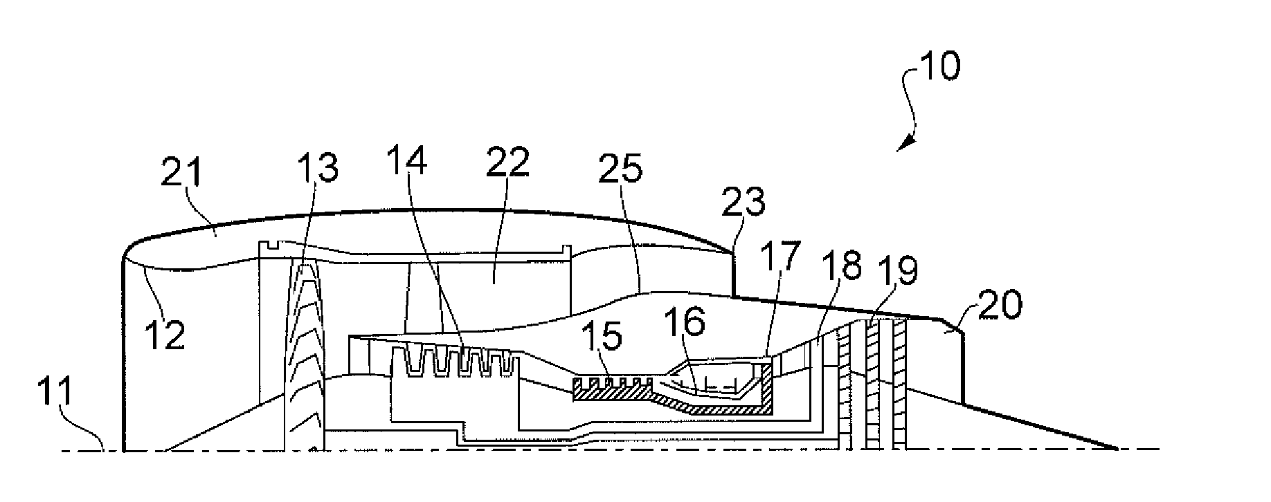
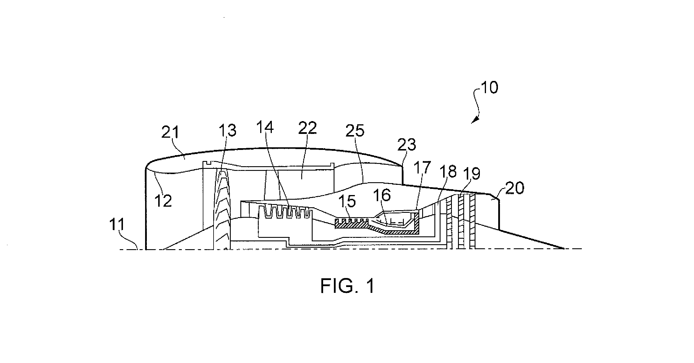
[0048]The present invention derives from the premise that it is possible to drive a booster and / or generator by the difference in relative rotation between the high-pressure and low-pressure spools of a gas turbine engine.

[0049]Gas turbine engines using the invention may operate substantially in the manner described above in relation to FIG. 1, with the exception that the intermediate-pressure turbine 18 and shaft may be removed. Accordingly the intermediate-pressure compressor 14 may be replaced with a booster assembly driven by a gearing as will be described below.

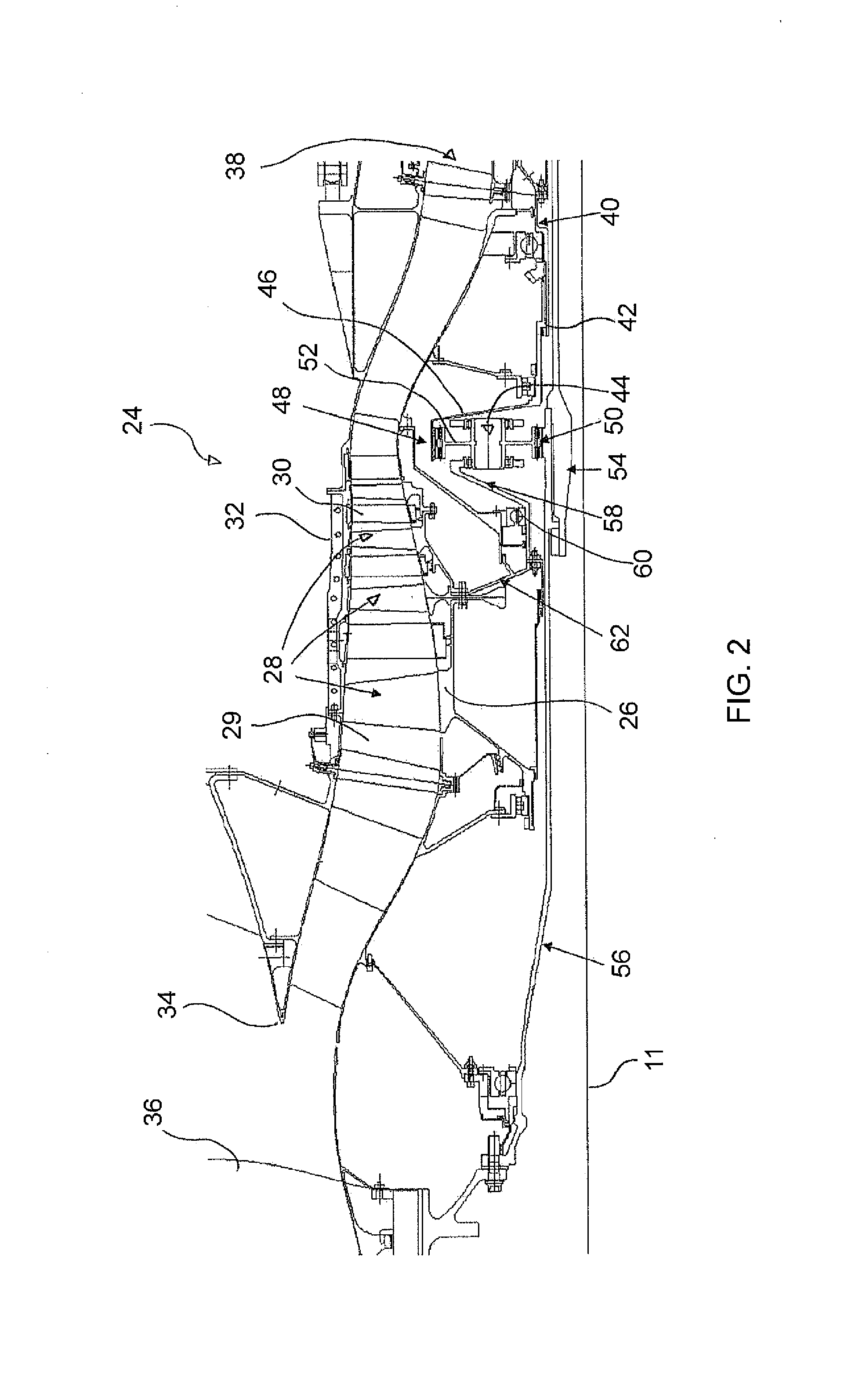
[0050]Turning to FIG. 2, there is shown a booster (i.e. compressor) arrangement 24 according to one example of the invention. The compressor portion of the arrangement comprises a rotor drum 26 having a plurality of compressor blades 28 depending radially outwardly therefrom at axially spaced locations. The compressor blades 28 are preferably provided as a plurality of rows or circumferential arrays of blades arranged ab...


PUM


Abstract

A booster assembly for a gas turbine engine having a first rotor assembly comprising a low pressure turbine drivingly connected to a fan via a first shaft and a second rotor assembly comprising a second turbine drivingly connected to a high pressure compressor via a second shaft. The booster assembly comprises a further compressor arranged to be disposed about said common axis between the fan and high-pressure compressor in a direction of flow and a gearing having first and second input rotors and an output rotor. The first input rotor is arranged to be driven by the first rotor assembly and the second input rotor is arranged to be driven by the second rotor assembly such that the output rotor drives the further compressor in dependence upon the difference in rotational speed between the first and second rotor assemblies.

Description

CROSS-REFERENCE TO RELATED APPLICATIONS[0001]This application is based upon and claims the benefit of priority from British Patent Application No. GB1219544.2 filed 31 Oct. 2012, the entire contents of which are incorporated by reference.BACKGROUND OF THE INVENTION[0002]1. Field of the Invention[0003]The present invention concerns compressors for gas turbine engines.[0004]2. Description of the Related Art[0005]With reference to FIG. 1, a conventional ducted fan gas turbine engine generally indicated at 10 has a principal and rotational axis 11. The engine 10 comprises, in axial flow series, an air intake 12, a propulsive fan 13, an intermediate pressure compressor 14, a high-pressure compressor 15, combustion equipment 16, a high-pressure turbine 17, and intermediate pressure turbine 18, a low-pressure turbine 19 and a core engine exhaust nozzle 20. A nacelle 21 generally surrounds the engine 10 and defines the intake 12, a bypass duct 22 and a bypass exhaust nozzle 23.[0006]The gas...

Claims


Application Information

Patent Timeline
Patent Type & Authority Applications(United States)
IPC IPC(8): F02C7/36
CPCF02C3/113F02K3/06F02C3/064F05D2260/40311F02K3/04F02C3/067F02C3/107F02C7/32F02C7/36
Inventor VENTER, GIDEON DANIEL
Owner ROLLS ROYCE DEUT LTD & CO KG
Why Eureka
Try Eureka