
Monolithic capacitor

Active Publication Date: 2014-06-05
MURATA MFG CO LTD
View PDF12 Cites 27 Cited by
  • Summary
  • Abstract
  • Description
  • Claims
  • Application Information

AI Technical Summary

Benefits of technology

The present invention provides a monolithic capacitor that reduces acoustic noise and allows for more flexibility in circuit design. The capacitor has a gap between its surfaces that allows for limited expansion and contraction caused by electrostriction, which prevents noise from being transmitted to the substrate on which the capacitor is mounted. This results in a quieter operation and a higher degree of freedom in circuit design. In summary, the invention provides a more efficient and effective monolithic capacitor for reducing noise and improving performance in various applications.

Problems solved by technology

Therefore, the expansion and contraction of the laminated body caused by electrostriction that occurs in the capacitive portions where the capacitor electrodes face each other is not easily transmitted to a substrate on which the monolithic capacitor is mounted.

Method used


Image

  • Monolithic capacitor
  • Monolithic capacitor
  • Monolithic capacitor

Examples


Embodiment Construction

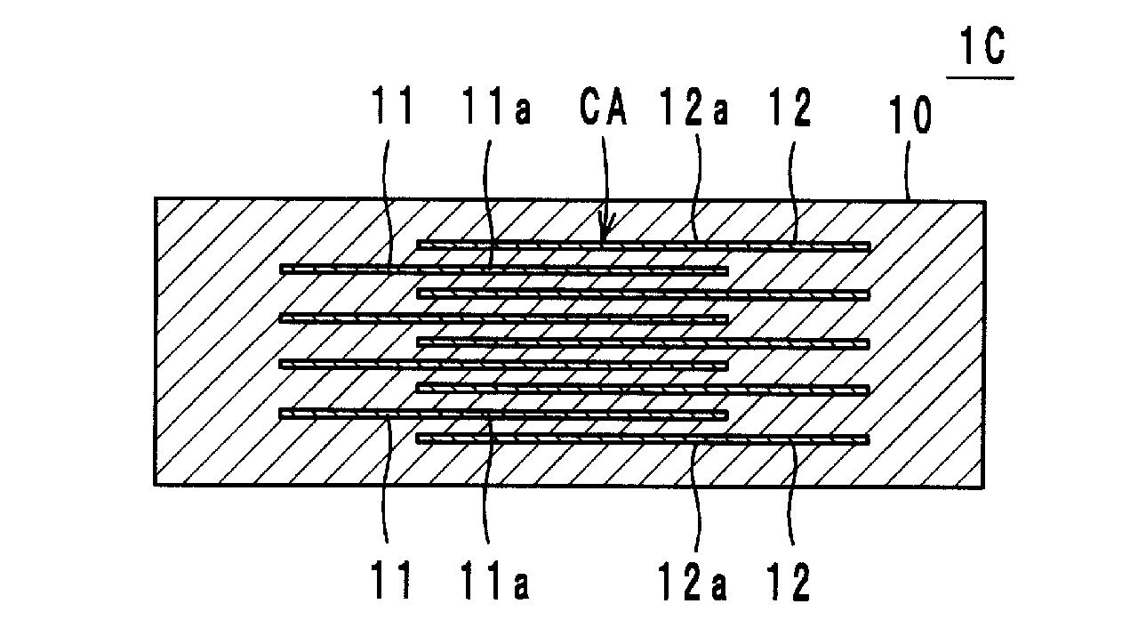
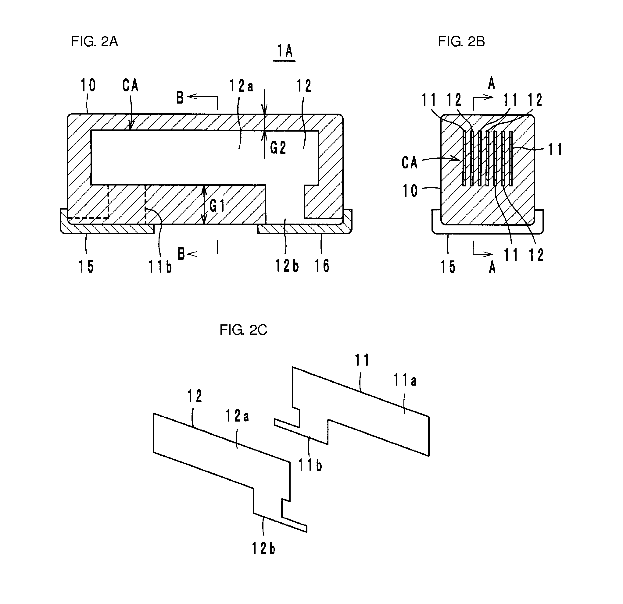
[0025]Preferred embodiments of a monolithic capacitor according to the present invention will now be described with reference to the accompanying drawings. Throughout the drawings, the same components and elements are denoted by the same reference numerals, and redundant description will be omitted.

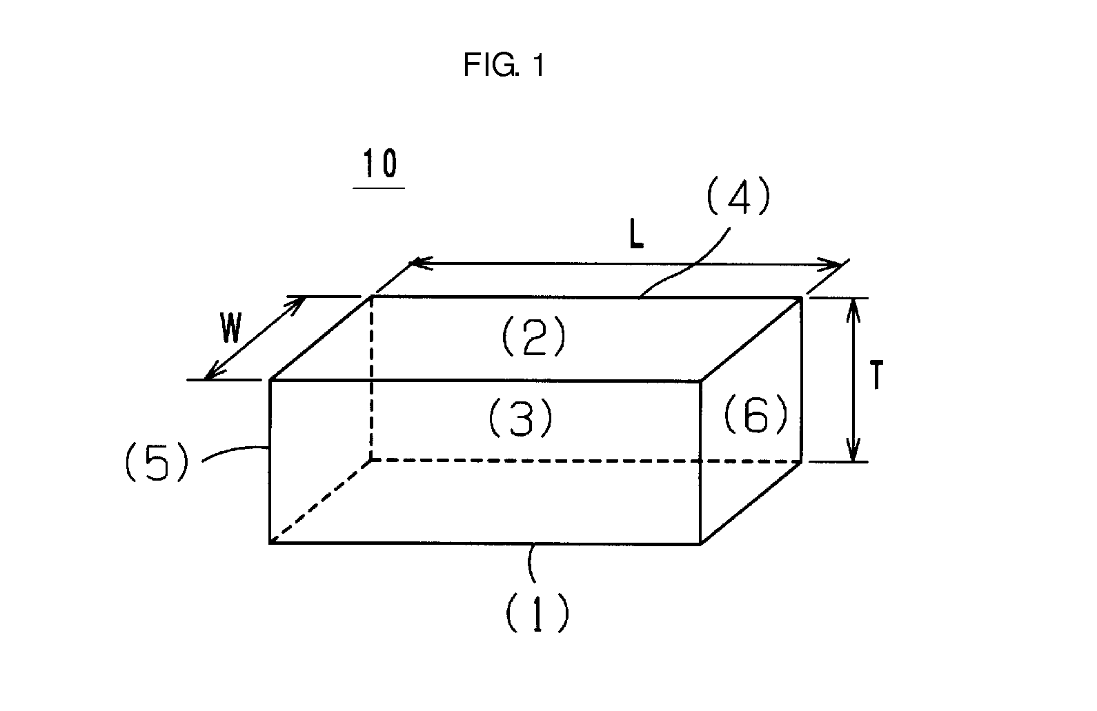
[0026]As illustrated in FIG. 1, a laminated body 10 included in a monolithic capacitor in accordance with a preferred embodiment of the present invention preferably in or substantially in the shape of a rectangular parallelepiped having six surfaces. The laminated body 10 is defined by stacking a plurality of dielectric layers. In the present preferred embodiment, a mounting surface (lower surface) is defined as a first surface (1); an upper surface opposite to the first surface is defined as a second surface (2); a front side and a back side orthogonal to both the first surface (1) and the second surface (2) and opposite each other are defined as a third surface (3) and a fourth surface ...


PUM


Abstract

A monolithic capacitor includes a laminated body including stacked dielectric layers and substantially in the shape of a rectangular parallelepiped, and including a first surface being a mounting surface, a second surface opposite to the first surface, opposing third and fourth surfaces orthogonal to the first and second surfaces, and opposing fifth and sixth surfaces orthogonal to the first to fourth surfaces; capacitor electrodes disposed in the laminated body and each including a capacitive portion and a lead portion extending therefrom to at least one surface of the laminated body, the capacitive portions facing each other with dielectric layers interposed therebetween; and first and second outer electrodes disposed on at least one surface of the laminated body and connected to the lead portions. A gap between the first surface and the capacitive portions is greater than a gap between the second surface and the capacitive portions.

Description

BACKGROUND OF THE INVENTION[0001]1. Field of the Invention[0002]The present invention relates to monolithic capacitors. In particular, the present invention relates to a monolithic capacitor that includes a laminated body including a plurality of dielectric layers stacked on each other; a plurality of capacitor electrodes disposed in the laminated body to face each other, with each of the dielectric layers interposed between adjacent ones of the capacitor electrodes; and a plurality of outer electrodes disposed on the surface of the laminated body and connected to the capacitor electrodes.[0003]2. Description of the Related Art[0004]In a monolithic capacitor formed by alternately stacking dielectric layers and capacitor electrodes, the application of a voltage thereto causes electrostriction in capacitive portions and expansion and contraction of a laminated body. In recent years, as monolithic capacitors have become smaller and their layers have become thinner, the intensity of an ...

Claims


Application Information

Patent Timeline
IPC IPC(8): H01G4/30H01G4/01
CPCH01G4/01H01G4/012H01G4/302
Inventor FUJII, YASUONISHIOKA, YOSHINAO
Owner MURATA MFG CO LTD
Learn More