Display system

a display panel and display angle technology, applied in the direction of arms, manufacturing tools, electrical apparatus casings/cabinets/drawers, etc., can solve the problems of not being able to see and operate the display panel in the position and angle of the display panel, and not being able to meet the needs of users (mainly drivers) to see and operate the display panel

Active Publication Date: 2014-06-05
FUJITSU GENERAL LTD
View PDF14 Cites 12 Cited by
  • Summary
  • Abstract
  • Description
  • Claims
  • Application Information

AI Technical Summary

Benefits of technology

[0013]Since the linearly-moving mechanism is provided to the side of the base member that defines a fixed direction of the rotation axis of the right-and-left changing mechanism, the fixed direction of the rotation axis of the right-and-left changing mechanism is not affected by movement of the up-and-down changing mechanism. Therefore, the fixed direction of the rotation axis of the right-and-left changing mechanism can be constant. Thus, even after the right-and-left changing mechanism moves, movement of the display panel can be consistent.

Problems solved by technology

Therefore, when the display system is installed in the installation area, a position and an angle of the display panel may not be suitable for the user (mainly driver) to see and operate the display panel.
Even if the user uses the technology mentioned above and rotates the display panel, using the rotation axis orthogonal to the display surface, there are many cases where the position and the angle of the display panel are not suitable for the user.

Method used


Image

  • Display system
  • Display system
  • Display system

Examples


Embodiment Construction

[0040]

[0041]An embodiment of the invention is hereinafter explained with reference to the drawings.

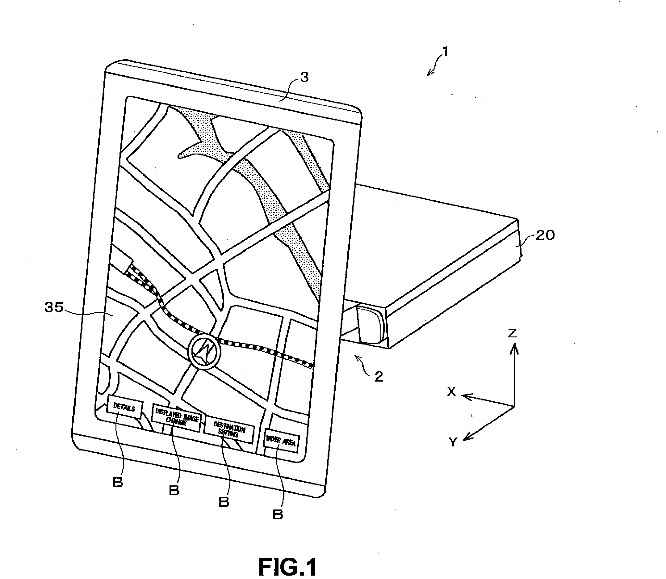
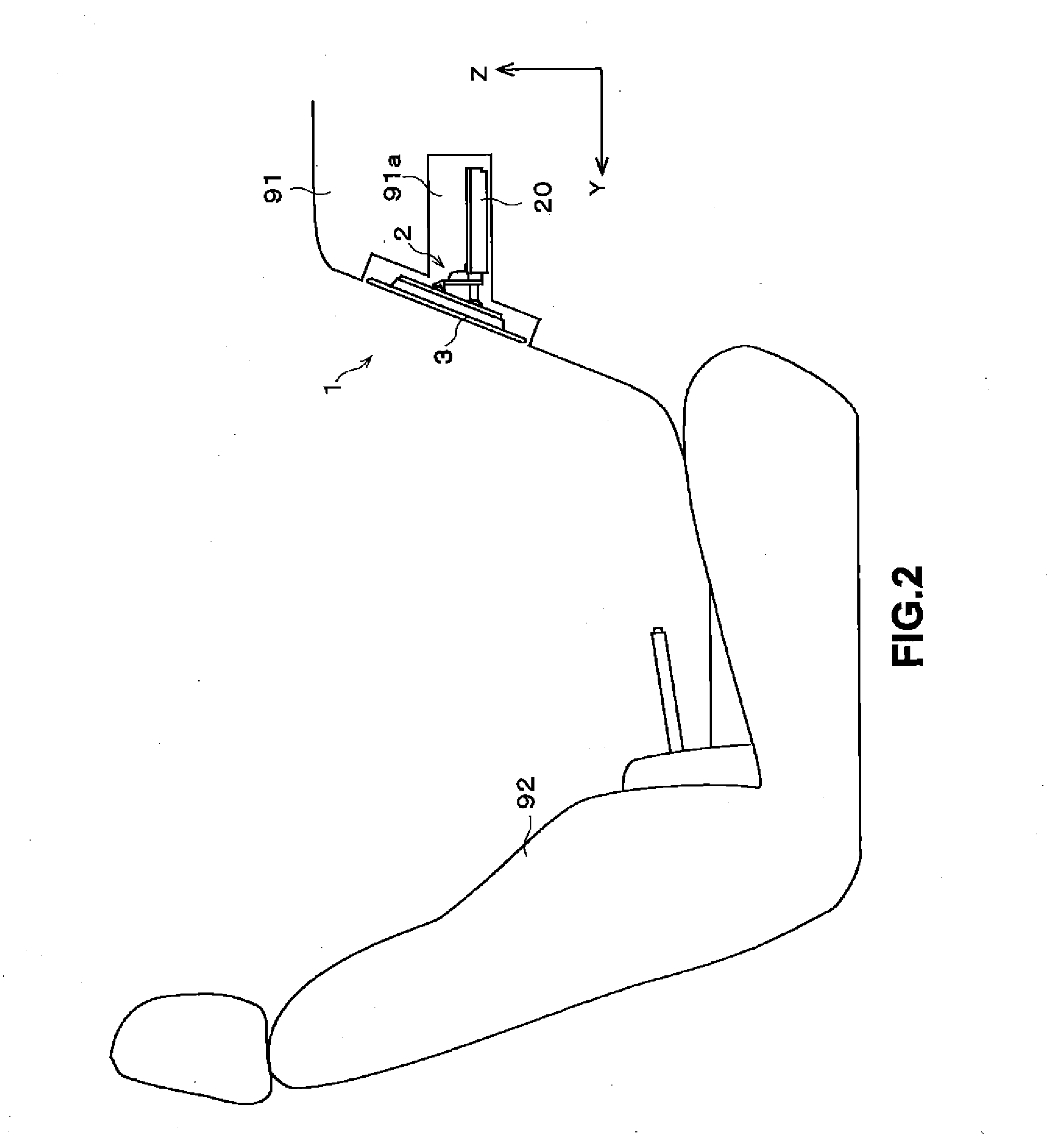
[0042]FIG. 1 shows a perspective view of an external appearance of a display system 1 that is an embodiment of the invention. The display system 1 is, for example, a vehicle-mounted apparatus that is mounted in a vehicle, such as a car, to be used in a cabin of the vehicle. The display system 1 includes, for example, a navigation function that provides a route to a destination, an audio function that outputs sound in the cabin, etc.

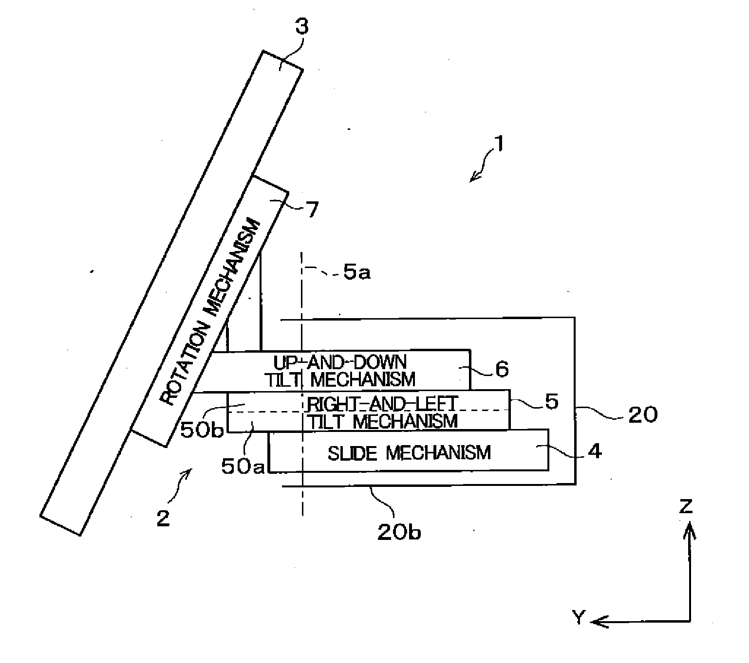
[0043]The display system 1 includes a display panel 3 that displays a variety of information and a base chassis 20 that is a support structure of the entire display system 1.

[0044]The display panel 3 is a thin display apparatus that includes a display 35, such as a liquid crystal display, as a display surface. The display surface of the display panel 3 is substantially rectangular having a longer side and a shorter side. A user (mainly a driver) in the vehic...


PUM


Abstract

A display system includes a display panel that displays information and a movement apparatus that moves the display panel. The movement apparatus includes: a slide mechanism configured to move the display panel linearly relative to a base chassis; a right-and-left tilt mechanism configured to change an angle of a display surface of the display panel in a right-and-left direction; an up-and-down tilt mechanism configured to change an angle of the display surface of the display panel in an up-and-down direction; and a rotation mechanism configured to rotate the display panel on a rotation axis orthogonal to the display surface of the display panel.

Description

BACKGROUND OF THE INVENTION[0001]1. Field of the Invention[0002]The invention relates to a technology that moves a display panel.[0003]2. Description of the Background Art[0004]Conventionally, a display system including a display panel having a navigation function and the like has been used in a vehicle. A user in the vehicle can obtain a variety of information by seeing the display panel. Moreover, generally, the display panel includes a touch panel and an operation portion so that the user can make various operations via the display panel.[0005]Normally, a display surface of such a display panel is rectangular, and the display surface is placed such that a longer side of the display surface is laid laterally. However, when a vertically-long image is displayed on the display surface, there is a case where visibility is improved if the display panel is placed such that the longer side of the display surface stands longitudinally. Therefore, a technology that allows the user to rotat...

Claims


Application Information

Patent Timeline
Patent Type & Authority Applications(United States)
IPC IPC(8): B25J18/00H05K7/02
CPCB25J18/00Y10S901/18H05K7/02B60K35/00B60K37/04B60K2370/1523B60K2370/822Y10T74/20329B60K2370/777
Inventor HIDA, MASASHI
Owner FUJITSU GENERAL LTD
Why Eureka
Try Eureka